Eureka AIR delivers breakthrough ideas for toughest innovation challenges, trusted by R&D personnel around the world.

Universal test fixture for surface mounted technology (SMT)-based diode components

A general-purpose testing and surface-mounting technology, which is applied in the direction of the measuring device casing, can solve the problems of increased production cost, extended test cycle, and low production efficiency, and achieves the effects of low cost, reduced test cycle extension, and simple structure

Active Publication Date: 2015-12-16
GUIZHOU AEROSPACE INST OF MEASURING & TESTING TECH
View PDF6 Cites 6 Cited by
  • Summary
  • Abstract
  • Description
  • Claims
  • Application Information

AI Technical Summary

Problems solved by technology

[0002] Surface mount two-pole components involve resistors, capacitors, diodes and other components, and the package sizes are various. For each package size, it is necessary to make corresponding test fixtures. Making a large number of fixtures consumes a lot of money, resulting in production Increased cost; when testing a new size component, the test fixture must be customized according to the size of the component, resulting in a longer test cycle; when testing, it is necessary to frequently place and remove the tested component in the test fixture, resulting in production efficiency not tall

Method used


Image

  • Universal test fixture for surface mounted technology (SMT)-based diode components
  • Universal test fixture for surface mounted technology (SMT)-based diode components
  • Universal test fixture for surface mounted technology (SMT)-based diode components

Examples


Embodiment Construction

[0018] The invention will be further introduced below in conjunction with the accompanying drawings and specific embodiments.

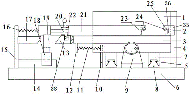
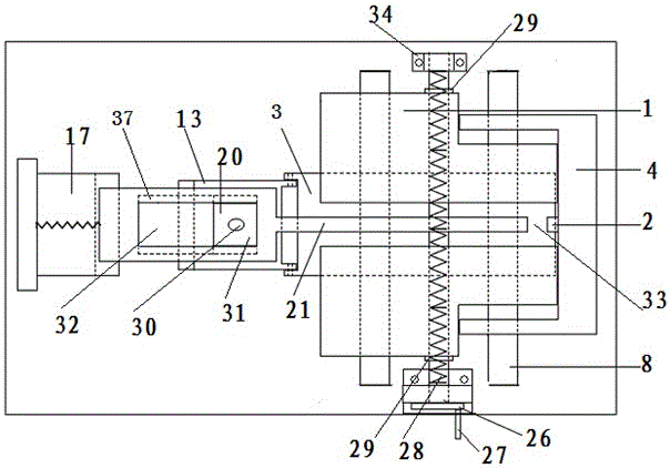
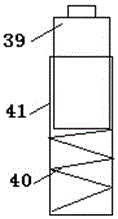
[0019] like Figure 1~Figure 3 As shown, a general test fixture for surface mount two-pole components includes a front and rear sliding positioning slider 1, an elastic test probe module 2 and a pull-out base plate 3, and the front and rear sliding positioning slider 1 adopts two sliders The front and back are symmetrically placed, and the screw nut set at the bottom drives the two sliders to move toward each other, and is connected to the guide rail pair 5, and a movable drawer bottom plate 3 is arranged near the bottom, and the drawer base plate 3 is embedded in the sliding body between the sliders. In the slot, the left end of the drawer bottom plate 3 is connected with a reset device that resets the drawer base plate after being drawn out, and an elastic test probe module 2 is arranged between the two sliders on it, and the elastic test probe modu...


PUM


Abstract

The invention discloses a universal test fixture for surface mounted technology (SMT)-based diode components, which comprises fore-and-aft sliding type positioning sliders, an elastic test probe module and a pull-out base plate. The fore-and-aft sliding type positioning sliders are composed of two sliders that are symmetrically arranged front and back. The two sliders are driven by screw-nut pairs arranged at the bottom thereof to move in opposite directions. The movable pull-out base plate is arranged close to the bottom. The left end of the movable pull-out base plate is connected with a reset device. On the pull-out base plate, the elastic test probe module is arranged between the two sliders. The elastic test probe module comprises a left test probe and a right test probe, wherein the two test probes are elastically flexible and are arranged right opposite to each other. According to the technical scheme of the invention, a to-be-tested component is placed in a variable placement groove. Under the fastening effect of the elastic test probes and the separating effect of the pull-out base plate, the to-be-tested component can be quickly replaced and tested. Meanwhile, by means of the two variable sliders and an elastic pressing bar, to-be-tested components of different specifications can be tested. Therefore, the testing efficiency and the testing precision are greatly improved. The universal test fixture is simple in structure, convenient to operate and use, and low in price.

Description

technical field [0001] The invention belongs to the technical field of electronic component testing devices, and relates to a universal testing fixture for surface-mounted two-pole components. Background technique [0002] Surface mount two-pole components involve resistors, capacitors, diodes and other components, and the package sizes are various. For each package size, it is necessary to make corresponding test fixtures. Making a large number of fixtures consumes a lot of money, resulting in production Increased cost; when testing a new size component, the test fixture must be customized according to the size of the component, resulting in a longer test cycle; when testing, it is necessary to frequently place and remove the tested component in the test fixture, resulting in production efficiency not tall. SUMMARY OF THE INVENTION [0003] The technical problem to be solved by the present invention is to provide a universal test fixture for surface-mounted diode compone...

Claims


Application Information

Patent Timeline
IPC IPC(8): G01R1/04
Inventor 范春帅陈尔鹏
Owner GUIZHOU AEROSPACE INST OF MEASURING & TESTING TECH
Why Eureka
Eureka Blog
Learn More