Wireless Vibration Target Classification and Recognition Device
A target classification and wireless vibration technology, applied in the direction of measuring devices, electrical devices, anti-theft alarm mechanical start, etc., can solve the problems of long-term low power consumption and other problems, to improve the survival time in the field, improve environmental adaptability, low power The effect of consumption design
- Summary
- Abstract
- Description
- Claims
- Application Information
AI Technical Summary
Problems solved by technology
Method used
Image

Examples
specific Embodiment approach 1
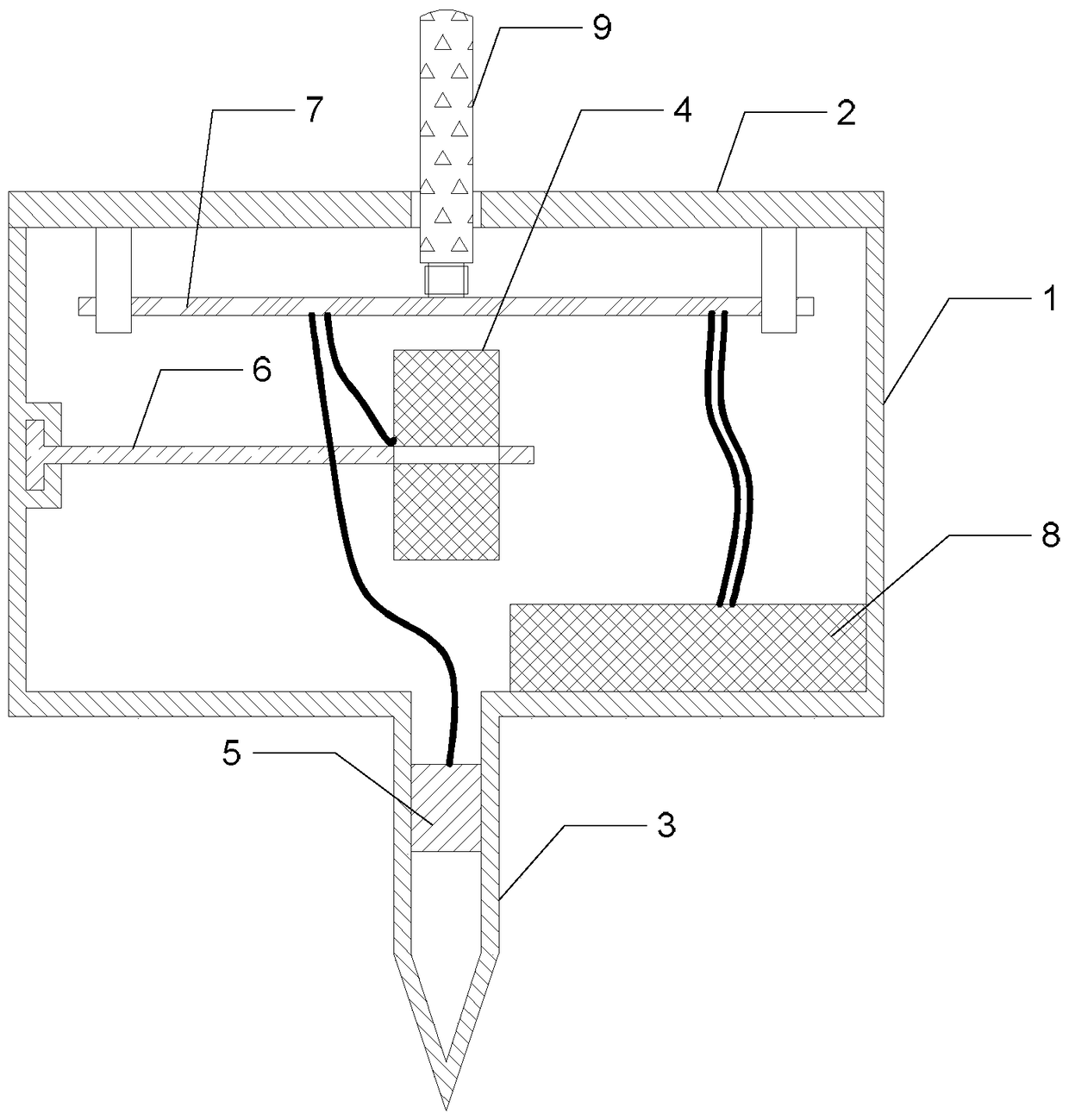
[0019] Specific implementation mode one: the following combination figure 1 Describe this embodiment. The wireless vibration target classification and recognition device described in this embodiment includes a housing 1, an upper cover 2, a hollow cone 3, a vibration sensor 4, an angle sensor 5, a vibration sensor carrier 6, and a circuit board. 7. Power supply 8 and antenna 9;
[0020] The housing 1 is in the shape of a barrel, the upper opening of the housing 1 is provided with an upper cover 2, the middle part of the lower end surface of the housing 1 is connected with the upper end of the hollow cone 3, and the inner cavity of the housing 1 is connected with the hollow cone 3. The inner cavity is connected; the angle sensor 5 is arranged on the inner side wall of the hollow vertebral body 3;
[0021] The arc-shaped head end of the vibration sensor carrier 6 is fixed on the side wall of the housing 1, and the suspended tail end of the vibration sensor carrier 6 is provided...
specific Embodiment approach 2
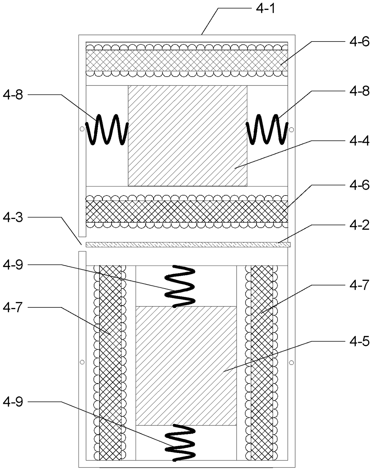
[0027] Specific implementation mode two: the following combination figure 2 Describe this embodiment, this embodiment will further explain Embodiment 1, the vibration sensor 4 includes a sensor housing 4-1, an insulating partition 4-2, a lead hole 4-3, a horizontal magnetic steel 4-4, a vertical magnetic steel 4-5, two sets of horizontal coils 4-6, two sets of vertical coils 4-7, two horizontal springs 4-8 and two vertical springs 4-9;
[0028] The sensor housing 4-1 is divided into upper and lower parts by the insulating partition 4-2, and a lead hole 4-3 is provided on the side wall of the sensor housing 4-1 outside the junction of the two; the upper part is a horizontal vibration monitoring chamber , the lower part is the vertical vibration monitoring chamber;
[0029] A horizontal magnetic steel 4-4 is arranged in the horizontal vibration monitoring cavity, and the left and right sides of the horizontal magnetic steel 4-4 are respectively connected to the left and right ...
specific Embodiment approach 3
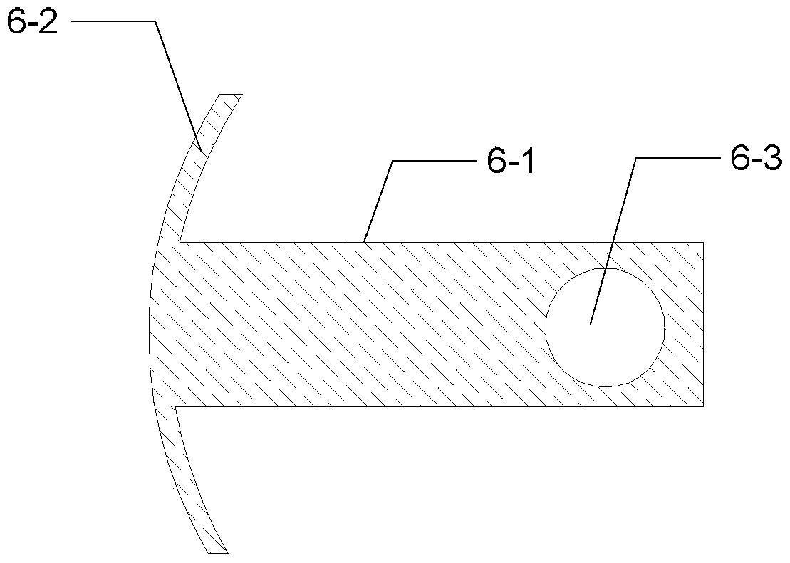
[0033] Specific implementation mode three: the following combination image 3 Describe this embodiment, this embodiment will further explain Embodiment 1, the vibration sensor carrier 6 includes an elastic beam 6-1, an arc-shaped head end 6-2 and a mounting hole 6-3, and the head end of the elastic beam 6-1 It is fixedly connected with the arc-shaped head end 6-2, and the arc-shaped head end 6-2 is horizontally screwed into the fixed part of the side wall of the housing 1, and is connected with the side wall of the housing 1 by means of an arc-shaped latch; the elastic beam 6- 1 and the arc-shaped head end 6-2 are integrated elastic beam structures;
[0034] The tail end of the elastic beam 6-1 is provided with a mounting hole 6-3, the mounting hole 6-3 is a through hole transparent up and down, and is used to place the vibration sensor 4, and the center of the through hole is located at the center of the housing 1. axis line.
[0035] The vibration sensor carrier 6 describe...
PUM
 Abstract
Description
Claims
Application Information
 - R&D
- Intellectual Property
- Life Sciences
- Materials
- Tech Scout
- Unparalleled Data Quality
- Higher Quality Content
- 60% Fewer Hallucinations
Browse by: Latest US Patents, China's latest patents, Technical Efficacy Thesaurus, Application Domain, Technology Topic, Popular Technical Reports.
© 2025 PatSnap. All rights reserved.Legal|Privacy policy|Modern Slavery Act Transparency Statement|Sitemap|About US| Contact US: help@patsnap.com