Spiral conveyer sealing device

A technology of screw conveyor and sealing device, applied in the field of chip conveying device and sealing device of screw conveyor, can solve the problems of small occupied space and outflow of cutting fluid, and achieve the effect of small occupied space, improved stability and high reliability

Active Publication Date: 2015-12-16
共享机床辅机(大连)有限公司
View PDF8 Cites 3 Cited by
  • Summary
  • Abstract
  • Description
  • Claims
  • Application Information

AI Technical Summary

Problems solved by technology

[0003] Aiming at the deficiencies of the prior art, the present invention provides a screw conveyor sealing device, which occupies a small space, solves the problem of cutting fluid outflow during use, solves the shaking of the connecting shaft when the screw rod shakes, and prolongs the reliability and reliability of the sealing device. Long life, reduce the noise of the screw conveying device

Method used


Image

  • Spiral conveyer sealing device

Examples


specific Embodiment approach

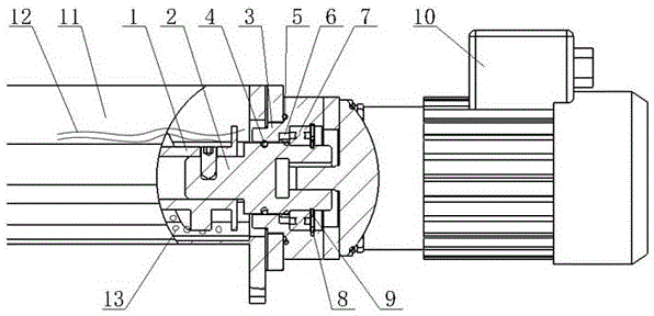
[0014] A sealing device for a screw conveyor, including a screw rod 1, a connecting shaft 2, a bearing seat 3, a small O-shaped sealing ring 4, a large O-shaped sealing ring 5, a lip-shaped sealing ring 6, a bearing 7, and an elastic retaining ring 8 for holes , shaft circlip 9, motor 10, spiral groove body 11, characterized in that the bearing seat 3 is fixed in the hole at the right end of the spiral groove body 11, wherein the left end of the bearing seat is a stepped structure, the first step surface and the The right end surface of the spiral groove body 11 is in contact, and the large O-shaped sealing ring 5 is fixed in the groove provided on the first step surface of the bearing seat 3. The lip seal ring 6 and the bearing 7 are installed in the bearing seat 3, and the lip seal The ring 6 is near the end of the screw rod 1, and the circlip 8 for the hole is installed in the bearing seat 3 to fix the lip seal ring 6 and the bearing 7; the connecting shaft 2 passes through ...


PUM


Abstract

The invention discloses a spiral conveyer sealing device. The spiral conveyer sealing device is characterized in that a bearing base is fixed in a hole at the right end of a spiral groove body; the left end of the bearing base is a step-shaped structure; a first step surface is contacted with a right end surface of the spiral groove body; a large O-shaped sealing ring is fixed in a groove in the first step surface of the bearing base; a lip-shaped sealing ring and a bearing are mounted in the bearing base; the lip-shaped sealing ring is near a spiral rod end; an elastic retainer ring for hole is mounted in the bearing base; a connecting shaft penetrates through the bearing base and the bearing, one end thereof is connected with a spiral rod, and the other end is connected with a motor, so that the spiral rod and the motor are connected as a whole through the connecting shaft; the connecting shaft is fixed in the bearing base through a contact part at the left end of the bearing base and an elastic retainer ring for shaft at the right end of the bearing base; and a small O-shaped sealing ring is fixed in a groove formed in the contact surface, corresponding to the contact part of the bearing base, of the connecting shaft. The spiral conveyer sealing device has the beneficial effects of solving the problem of outward flowing of cutting liquid in the use process, improving the reliability of the sealing device and prolonging the service life of the sealing device.

Description

technical field [0001] The invention belongs to the field of machine tool processing, and relates to a chip conveying device containing a large amount of cutting fluid, in particular to a screw conveyor sealing device. Background technique [0002] In the field of machine tool processing, cutting and grinding of metal materials generally use cutting fluid to cool, lubricate, and clean tools and workpieces. Chips generated during processing are mixed with cutting fluid inside the machine tool. Chip conveying devices are used together with cutting fluid, The chips are conveyed together outside the machine for disposal. Due to the limited space inside the machine tool, screw conveyors are usually used to transport the mixture of the two to the next level of conveying device or chip collector. During the conveying process, the rotating shaft is immersed in the cutting fluid. Due to the action of chips, there is no fixed device at the front end of the screw rod to swing. , When ...

Claims


Application Information

Patent Timeline
Patent Type & Authority Applications(China)
IPC IPC(8): B65G33/32
Inventor 铁彦清孙冠琳马同堂赵龙何国峰
Owner 共享机床辅机(大连)有限公司
Why Eureka
Try Eureka