
A self-deformable robot module unit and a snake-like robot

A snake-shaped robot and modular unit technology, applied in the field of robotics, can solve the problems of less motion forms, less robot configurations, and inability to biologically simulate motion, etc., and achieve the effects of strong motion ability, reasonable design and simple structure

Active Publication Date: 2017-03-08
HARBIN INST OF TECH
View PDF5 Cites 2 Cited by
  • Summary
  • Abstract
  • Description
  • Claims
  • Application Information

AI Technical Summary

Problems solved by technology

[0003] The present invention is to solve the problem that the structure of the existing robot module unit is complicated, the robot configuration is less, resulting in less movement forms, the movement cannot be more vividly simulated in biology, and the problem of limited work tasks can only be completed, and further proposes a Self-morphing robot modular unit and snake-like robot

Method used


Image

  • A self-deformable robot module unit and a snake-like robot
  • A self-deformable robot module unit and a snake-like robot
  • A self-deformable robot module unit and a snake-like robot

Examples


specific Embodiment approach 1

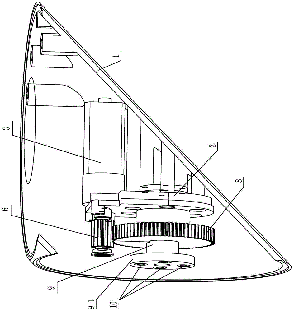
[0010] Embodiment 1: Combining Figure 1-Figure 3 Description, a self-deforming robot module unit in this embodiment includes a housing 1, a motor base 2, a motor 3, a first gear 6, a second gear 8, an output shaft 9, a cover 15, and a plurality of permanent magnets 10;

[0011] A motor base 2, a motor 3, a first gear 6, a second gear 8, an output shaft 9 and a plurality of permanent magnets 10 are arranged in the housing 1;

[0012] The motor base 2 is installed on the housing 1, the motor 3 is installed on the motor base 2, the output shaft 9 is rotatably installed on the motor base 2, the output shaft of the motor 3 is fixedly mounted with the first gear 6, and the second gear 8 is fixedly mounted on the motor base 2. On the output shaft 9, the first gear 6 meshes with the second gear 8, the cover plate 15 covers the surface opening of the casing 1, the cover plate 15 is made of martensitic stainless steel or ferritic stainless steel, and the end of the output shaft 9 The ...

specific Embodiment approach 2

[0014] Specific implementation mode 2: Combining figure 1 Note that the motor 3 of the present embodiment is a DC motor. This arrangement is cheap and easy to obtain, small in size and convenient to use, and a DC geared motor can be used. Others are the same as the first embodiment.

specific Embodiment approach 3

[0015] Specific implementation three: combination figure 1 It is explained that the plurality of permanent magnets 10 in this embodiment are glued on the disc structure 9 - 1 at the end of the output shaft 9 . With this setting, the connection is convenient and the use is reliable. Others are the same as in the first or second embodiment.


PUM


Abstract

The invention discloses a self-transformation robot module unit and a snakelike robot, relates to the robot technology and aims at solving the problems that existing robot module units are complex in structure, little in configuration of constituted robots, few in caused movement form and incapable of simulating movement biologically in a more vivid mode, and only limited work tasks can be completed. The robot module unit comprises a shell, a motor base, a motor, a first gear, a second gear, an output shaft, a cover plate and multiple permanent magnets; the motor base, the motor, the first gear, the second gear, the output shaft and the multiple permanent magnets are arranged in the shell; the motor base is installed on the shell, the motor is installed on the motor base, and the output shaft is rotatably installed on the motor base; the first gear is fixed installed on the output shaft of the motor, the second gear is fixedly installed on the output shaft, the first gear is meshed with the second gear, the cover plate is arranged on a surface opening in the shell in a covering mode, the end of the output shaft is of a disc type structure, and the multiple permanent magnets are evenly installed on the outer end face of the disc type structure in the circumferential direction of the output shaft. The self-transformation robot module unit is used for the robot.

Description

technical field [0001] The invention relates to robot technology, in particular to a self-deforming robot module unit and a snake-shaped robot. Background technique [0002] With the development of modern science and technology, the robot technology has also been continuously improved, and the robot has also become a research hotspot. Modular robots are easy to implement a variety of motion modes and can work in different tasks and environments. At present, for modular robots, the design of modular units is a crucial part. Most of the existing modular designs are based on spherical or cube designs with complex structures. This modular design will limit the potential of the robot to form. Configurations and movement forms, such as spherical and square, the adjacent joints need a connection mechanism, which cannot be closely connected, and the effect is not good in the bionic snake shape, and cannot be more vividly simulated in biology. Limited work assignments. SUMMARY OF...

Claims


Application Information

Patent Timeline
Patent Type & Authority Patents(China)
IPC IPC(8): B25J17/00B25J9/06
CPCB25J9/065
Inventor 朱延河张宇赵杰
Owner HARBIN INST OF TECH
Learn More