
A simple welding manipulator

A welding manipulator and simple technology, applied in welding equipment, auxiliary welding equipment, welding/cutting auxiliary equipment, etc., can solve the problem that it is difficult to meet the requirements of welding seam flatness, welding quality is difficult to be guaranteed, and the shell of electric welding machine is not grounded and grounded, etc. problems, to achieve the effect of improving working conditions, simple structure, and improving welding quality

Active Publication Date: 2017-01-11
CSSC MES DIESEL
View PDF6 Cites 0 Cited by
  • Summary
  • Abstract
  • Description
  • Claims
  • Application Information

AI Technical Summary

Problems solved by technology

However, there are many shortcomings in welding steel pipes with hand-held welding torches: first, electric welding is a special operation, because many welders often have unsafe behaviors in violation of the "Operation Regulations" in the operation, resulting in many hidden dangers of accidents at the electric welding operation site, For example, the shell of the electric welding machine is not grounded or the grounding is unreliable, the terminal post is exposed without insulation treatment, the welding torch exposes the lead connector conductor without insulation treatment, the welding torch soaks the lead wire in water, etc. There are certain hidden dangers to the personal safety of myself and others; secondly, the hand-held welding torch method has higher requirements for welders, and it is necessary to maintain the posture of holding the welding torch for a long time. Mechanical labor is easy to cause fatigue and cannot concentrate on work, thus It leads to a decrease in welding speed and low work efficiency; finally, the hand-held welding torch will shake the welding torch during the welding process, which makes it difficult to meet the flatness requirements of the weld seam and also affects the aesthetics of welding, so the welding quality is difficult to be guaranteed

Method used


Image

  • A simple welding manipulator
  • A simple welding manipulator
  • A simple welding manipulator

Examples


Embodiment Construction

[0027] The present invention will be described in detail below in conjunction with the accompanying drawings and specific embodiments. The following embodiments introduce a simple welding manipulator, but the scope of protection of the present invention is not limited to the following embodiments. All equivalent changes and modifications made according to the content of this specification belong to the technical scope of the patent application of the present invention.

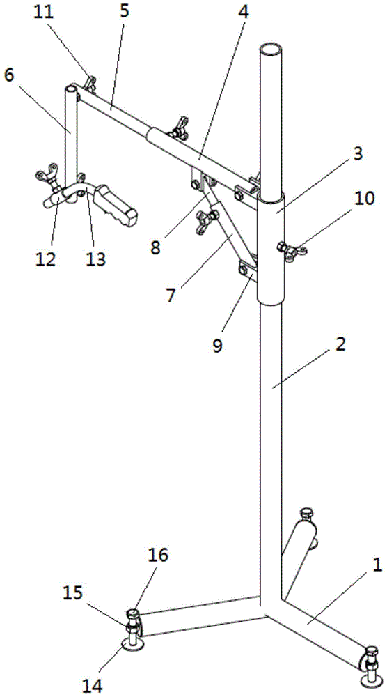
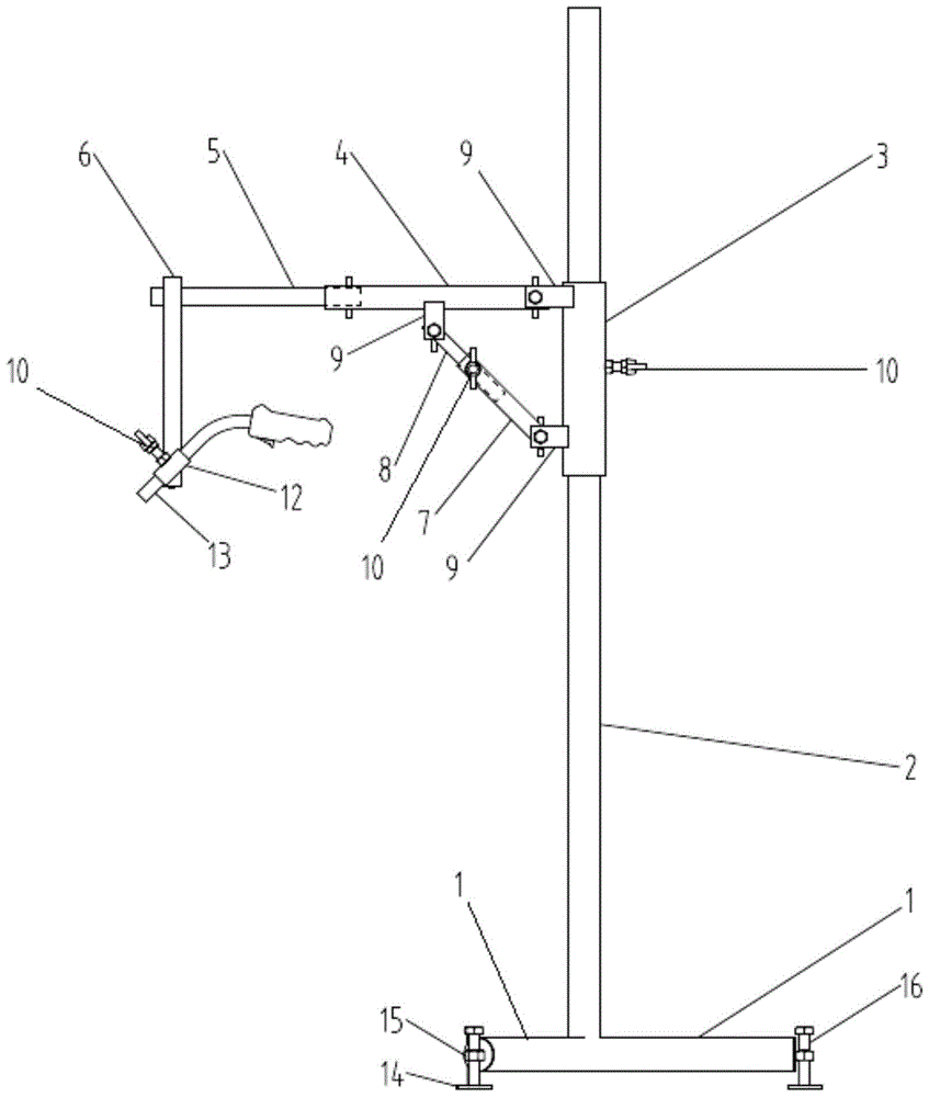
[0028] Please refer to figure 1 with figure 2 , the diagram shows a simple welding manipulator including a base part, a multi-degree-of-freedom manipulator part and a welding torch fixing part. The base part is placed on the ground, the multi-degree-of-freedom mechanical arm part is connected to the base part and can realize vertical up-and-down movement and horizontal turning motion along the base part, and the end of the multi-degree-of-freedom mechanical arm part passes through the multi-degree-of-freedom...


PUM


Abstract

A simple welding manipulator comprises a base assembly, a multi-freedom-degree mechanical arm assembly and a welding gun fixing assembly. The base assembly is installed on the ground, the multi-freedom-degree mechanical arm assembly is connected with the base assembly and can achieve vertical up-and-down motion and horizontal circumnutation along the base assembly, the tail end of the multi-freedom-degree mechanical arm assembly is positioned at any position in space through relative motion among internal elements of the multi-freedom-degree mechanical arm assembly, the welding gun fixing assembly is connected to the tail end of the multi-freedom-degree mechanical arm assembly and used for installing a welding gun, and the welding gun can arrive at any needed working positions and angles through combination of regulating motion of the multi-freedom-degree mechanical arm assembly and regulating motion of the welding gun fixing assembly. According to the simple welding manipulator, the effects of improving the welding quality, labor conditions, working efficiency and economic benefits are achieved, and the advantages of being high in stability, large in positioning range, simple in structure, convenient and fast to operate, low in manufacturing cost and the like are achieved.

Description

technical field [0001] The invention relates to a welding process equipment, in particular to a simple welding manipulator used for clamping a welding torch during the welding operation of a steel pipe of a marine low-speed diesel engine, and belongs to the field of welding technology. Background technique [0002] In the manufacturing process of marine low-speed diesel engines, various steel pipes need to be welded, such as main lubricating oil pipes, air cooler inlet and return pipes, LDCL cooling water pipes, cylinder head cooling water inlet and return pipes, cylinder liner cooling water inlet and return pipes and other pipe fittings. Various pipe fittings have different functions: the main lubricating oil pipe is used to deliver lubricating oil for the whole diesel engine, which is located on the exhaust side of the machine base and the free end of the cylinder block of the frame, and needs to be welded and connected in combination with pipe bending; the air cooler The ...

Claims


Application Information

Patent Timeline
Patent Type & Authority Patents(China)
IPC IPC(8): B23K37/02
CPCB23K37/0229
Inventor 瞿董明张勤
Owner CSSC MES DIESEL
Learn More