
X-ray CT device

An X-ray and X-ray tube technology, applied in the field of X-ray CT devices, can solve problems such as image contrast reduction

Inactive Publication Date: 2015-12-09
TOSHIBA MEDICAL SYST CORP
View PDF15 Cites 3 Cited by
  • Summary
  • Abstract
  • Description
  • Claims
  • Application Information

AI Technical Summary

Problems solved by technology

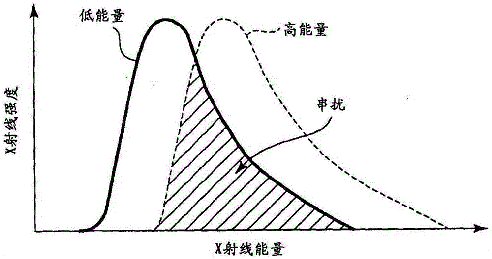
[0008] In the conventional spectral CT, there is a problem that the contrast of the image is lowered due to the so-called energy crosstalk in which the energy spectrum of the low-energy X-ray and the energy spectrum of the high-energy X-ray overlap.

Method used


Image

  • X-ray CT device
  • X-ray CT device
  • X-ray CT device

Examples


specific example 1

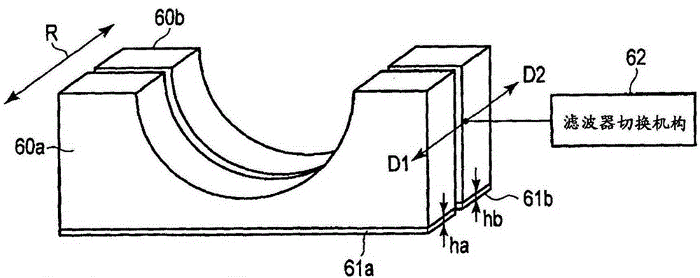
[0071] As a specific example 1, the low tube voltage Va is set to 40kV, the high tube voltage Vb is set to 50kV, the substance Xa is set to iodine, the substance Xb is set to indium and zinc, and the thickness ha is set to It is 250 μm and the thickness hb is set to 300 μm (indium 150 μm+zinc 150 μm).

[0072] Figure 4 is the absorption coefficient CI of iodine, the energy spectrum Sa of X-rays emitted from the X-ray filter 61a when a low tube voltage Va is applied to the X-ray tube 5, and the energy spectrum Sa of X-rays emitted from the X-ray filter 61a when a high-tube voltage Vb is applied to the X-ray tube 5. The graph of the energy spectrum Sb of the X-ray emitted by the detector 61b. The horizontal axis is energy (KeV), the left vertical axis is the normalized number of photons, and the right vertical axis is the absorption coefficient (1 / cm).

[0073]The K absorption edge of iodine appears at about 33keV. Before and after this K absorption end, the absorption coeff...

specific example 2

[0077] As a specific example 2, the low tube voltage Va is set to 60kV, the high tube voltage Vb is set to 70kV, the substance Xa is set to gadolinium, the substance Xb is set to iodine and lead, and the thickness ha is set to The thickness hb is 300 μm and the thickness hb is set to 800 μm (500 μm iodine+300 μm lead).

[0078] Figure 5 is the absorption coefficient CGd of gadolinium, the energy spectrum Sa of X-rays emitted from the X-ray filter 61a when a low tube voltage Va is applied to the X-ray tube 5, and the energy spectrum Sa of X-rays emitted from the X-ray filter 61a when a high-tube voltage Vb is applied to the X-ray tube 5. The graph of the energy spectrum Sb of the X-ray emitted by the detector 61b. The horizontal axis is energy (KeV), the left vertical axis is the normalized number of photons, and the right vertical axis is the absorption coefficient (1 / cm).

[0079] The K absorption end of gadolinium occurs at about 50keV. Before and after this K absorption...


PUM


Abstract

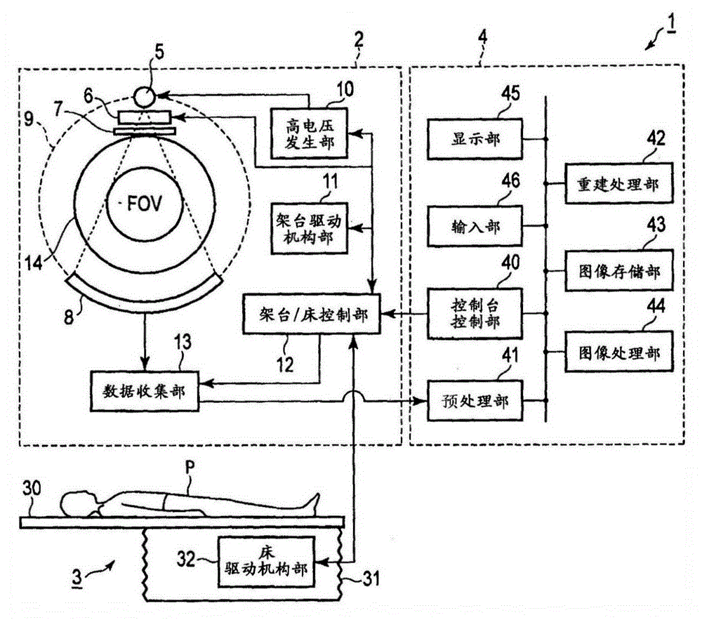
The purpose of the present invention is to reduce energy crosstalk of X-rays generated with different tube voltages. An X-ray CT device comprises: an X-ray tube (5); a high voltage generator (10) which selectively generates first and second tube voltages; a first filter (61a) for radiation quality adjustment which is formed with a substance that has substantially the same atomic number as a contrasting substance; a second filter (61b) for radiation quality adjustment which is formed with a substance that is different from the contrasting substance; a filter switching mechanism (62) for switching between the first and second filters; an X-ray detector (8); a reconstruction unit (42) which reconstructs an image on the basis of projected data from the output of the X-ray detector; and a control unit (12) which controls the high voltage generator and the filter switching mechanism in order to synchronize the switching between the first and second tube voltages and the switching between the first and second filters.

Description

technical field [0001] An embodiment of the present invention relates to an X-ray CT (Computed Tomography: computerized tomography) apparatus. Background technique [0002] There is an X-ray CT apparatus that performs dual-energy scanning. In dual-energy scanning, the X-ray CT device uses X-rays whose energy spectrum is distributed in the low-energy region (hereinafter, low-energy X-rays) to collect projection data during the scanning of the subject, and uses the energy spectrum distribution X-rays in high-energy regions (hereinafter, high-energy X-rays) are used to collect projection data. By using the projection data collected in this way, it is possible to perform imaging utilizing the difference in X-ray absorption coefficient of substances constituting the subject, for example, to obtain an image in which a region contrasted with a contrast medium is separated from other regions with high contrast. [0003] As a system configuration of an X-ray CT apparatus that perfo...

Claims


Application Information

Patent Timeline
IPC IPC(8): A61B6/03
CPCA61B6/06A61B6/032A61B6/482A61B6/4042A61B6/405A61B6/481A61B6/5211A61B6/54
Inventor 田村惠美齐藤泰男高山卓三宫崎博明中井宏章
Owner TOSHIBA MEDICAL SYST CORP
Learn More