Laser dissipation spot path, two-color and three-color laser source
A technology of laser light source and speckle dissipation, applied in optics, color TV, optical components, etc., to achieve the effect of reducing accumulation phenomenon, reducing light decay phenomenon and prolonging service life
- Summary
- Abstract
- Description
- Claims
- Application Information
AI Technical Summary
Problems solved by technology
Method used
Image
Examples
Embodiment 1
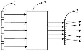
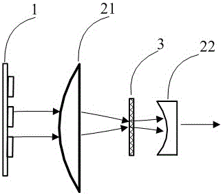
[0026] Embodiment 1 of the present invention provides a laser speckle dissipated optical path, such as figure 2 As shown, the laser output light emitted by the front-end laser or the laser array 1 is received, and the laser output light sequentially passes through the first shrinking lens 21 and the second shrinking lens 22 to reduce the beam, so that the laser spot area zoom out. And, the laser output light also passes through the diffusion sheet 3 located between the first beam reduction lens 21 and the second beam reduction lens 22, which is used to diffuse the laser beam, generate more spatial random phases, and play a role in dissipating speckles. Function, preferably, the diffuser is controlled to rotate or translate, and the diffuser in a moving state has a better speckle dissipation effect than a fixed diffuser.
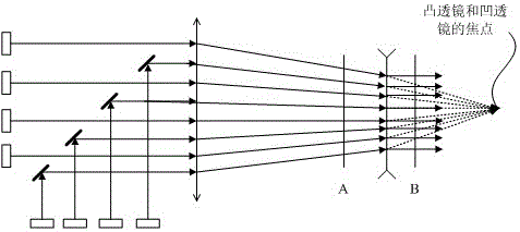
[0027] In specific implementation, such as image 3 As shown, the first beam shrinking lens 21 usually uses a large convex lens to receive all the laser b...
Embodiment 2
[0035] Embodiment 2 of the present invention differs from Embodiment 1 in that the second beam reducing lens is a convex lens or a convex lens combination composed of two convex lenses, wherein the convex lens or the convex lens combination composed of two convex lenses is combined with the first beam reducing lens relative settings. like Figure 4 As shown, the convex lens assembly 22 is located behind the diffuser 3 and is set opposite to the first beam reducing lens-convex lens.
[0036]After the laser beam passes through the diffuser 3, the light is in a divergent state, the first convex lens in the convex lens combination 22 can collimate the divergent laser beam, and the second convex lens can converge the collimated parallel beam again. The function can intensify the beam shrinkage and meet the irradiation requirements of small spots.
[0037] The above-mentioned combination of convex lenses can also be replaced with a piece of convex lens, both of which can play the ...
Embodiment 3
[0040] Embodiment 3 of the present invention provides a two-color laser light source, such as Figure 5 As shown, include blue laser 11, red laser 12, send out blue laser and red laser respectively, in the red laser exit light path, be provided with the light path of laser dispersing spot as described in embodiment 2, be provided with such as in the blue laser light path The optical path of the laser speckle disappearance described in Embodiment 1 is only a specific example in the embodiment of the present invention. It is also possible to set the laser speckle light path as described in Embodiment 1 in the red laser exit light path, and set the laser speckle light path as described in Embodiment 2 in the blue laser exit light path. Alternatively, since the human eye is more sensitive to the speckle effect of the red laser, the laser speckle-eliminating optical path as described in Embodiment 1 or 2 may also be provided only for the red laser emitting optical path.
[0041] S...
PUM
| Property | Measurement | Unit |
|---|---|---|
| Area | aaaaa | aaaaa |
Abstract
Description
Claims
Application Information
 - R&D Engineer
- R&D Manager
- IP Professional
- Industry Leading Data Capabilities
- Powerful AI technology
- Patent DNA Extraction
Browse by: Latest US Patents, China's latest patents, Technical Efficacy Thesaurus, Application Domain, Technology Topic, Popular Technical Reports.
© 2024 PatSnap. All rights reserved.Legal|Privacy policy|Modern Slavery Act Transparency Statement|Sitemap|About US| Contact US: help@patsnap.com


