
An Experimental Method for Methane Huff and Puff Assisted by Foam Oil in Thin Heavy Oil Reservoirs

The technology of a heavy oil reservoir and an experimental method is applied in the field of foam oil-assisted methane huff and puff in thin-layer heavy oil reservoirs, which can solve the problem of low recovery factor, and achieve the advantages of improving recovery factor, improving development effect, and increasing formation pressure. Effect

Active Publication Date: 2016-11-09
CHINA UNIV OF PETROLEUM (EAST CHINA)
View PDF5 Cites 0 Cited by
  • Summary
  • Abstract
  • Description
  • Claims
  • Application Information

AI Technical Summary

Problems solved by technology

The present invention introduces the phenomenon of foam oil increasing oil into the solvent huff and puff process of conventional heavy oil reservoirs to solve the problem of low recovery rate of existing oilfields in thin-layer heavy oil reservoirs

Method used


Image

  • An Experimental Method for Methane Huff and Puff Assisted by Foam Oil in Thin Heavy Oil Reservoirs
  • An Experimental Method for Methane Huff and Puff Assisted by Foam Oil in Thin Heavy Oil Reservoirs
  • An Experimental Method for Methane Huff and Puff Assisted by Foam Oil in Thin Heavy Oil Reservoirs

Examples


example 1

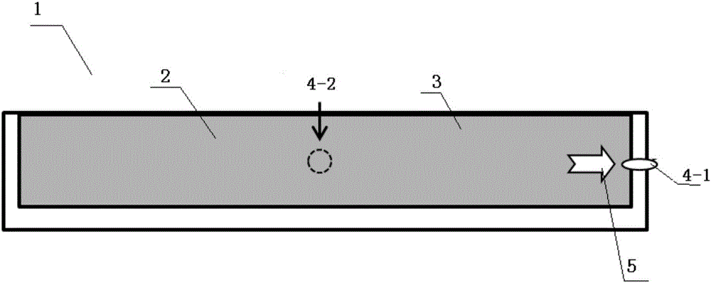
[0058] An experimental method for foam oil-assisted methane huff and puff in thin-layer heavy oil reservoirs. The experimental method uses a one-dimensional visual sand filling model 1, including a sand filling cavity 2 filled with quartz sand layers, and a sand filling cavity 2 in the sand filling cavity 2. A plurality of injection / production ports 4-1 are arranged around, and the liquid in the sand filling cavity 2 flows along a one-dimensional direction; the experimental method includes the following steps:

[0059] 1) inject formation crude oil into the quartz sand layer 3 of the described sand filling chamber 2, so that the model pressure is the formation pressure of the thin-bed heavy oil reservoir to be simulated; from figure 1 The shown injection / production port 4-1 injects crude oil into the formation, so that the sand filling model pressure is 430 psig formation pressure;

[0060] 2) Heavy oil decompression and cold recovery stage: depressurization and cold recovery ...

example 2

[0100] The experimental method as described in Example 1, wherein, in this example, the one-dimensional visual sand filling model used in the experiment is the same as Example 1, and the difference is that:

[0101] The porosity, permeability and original oil saturation of the one-dimensional visualized sand filling model after sand filling in the step 1) are 35.22% and 33.33 μm respectively 2 and 89%.

[0102] The step 2) in the step-down cold recovery recovery rate R 冷采 was 30.04%.

[0103] In described step 3), concrete steps are as follows:

[0104] First, inject methane gas, the injection pressure is greater than 650 psig, and the gas injection volume is 4759 cm 3 , the sand filling model pressure before braising is 367psig;

[0105] Next, inject the oil-soluble surfactant solution that makes described viscous oil form foam oil, injection pressure is 50psig, and concentration is 0.5wt%;

[0106] Finally, the distance from the front edge of the oil-soluble surfactant ...


PUM


Abstract

The invention relates to an experimental method for foam oil assisted methane huff-and-puff of a thin heavy oil reservoir. The method includes the following steps: an injection phase that in-place oil is injected to a quartz sand layer of a sand filling cavity; a pressure reduction and cold production phase of heavy oil; a foam oil assisted methane huff-and-puff injection phase; a soaking phase; a production phase; and a multi-round huff-and-puff phase. The injection phase: firstly, an oil soluble surfactant solution which can form the foam oil is injected, and then methane gas is injected; the formation pressure is increased; and a contact area between the surfactant solution and crude oil is expanded. The multi-round huff-and-puff phase: according to distribution of remaining oil, an injection location is changed, and the contact area between the surfactant as well as the methane gas and the crude oil is expanded. According to the experimental method of the invention, the problems that the formation pressure is quickly decreased in the conventional methane huff-and-puff production phase, the viscosity of crude oil is increased again, thermodynamic methods for developing the thin heavy oil reservoir cause severe thermal losses and high investment cost can be overcome. The method has a good application prospect for development of the thin heavy oil reservoir.

Description

technical field [0001] The invention relates to an experimental method for foam oil-assisted methane huff and puff in thin-layer heavy oil reservoirs, and belongs to the technical field of heavy oil reservoir exploitation. Background technique [0002] my country is very rich in heavy oil resources, with proven and controlled reserves of more than 1.9 billion tons, mainly distributed in more than a dozen oil fields including Liaohe, Xinjiang, Shengli, and Henan. With the continuous improvement of the exploration degree of conventional oil and gas resources and the increasing difficulty of development, the effective development of heavy oil resources has been paid more and more attention. [0003] The flow performance of underground heavy oil in my country is generally poor, or has no flow ability at all. At present, steam huff and puff, steam flooding and SAGD are usually used to reduce the viscosity of heavy oil. However, for thin heavy oil reservoirs, due to Due to serious...

Claims


Application Information

Patent Timeline
Patent Type & Authority Patents(China)
IPC IPC(8): E21B43/22
Inventor 孙晓飞张艳玉董明哲林承焰方潇孟勇李冬冬许凤桐冯金良王士林吴洁田丰
Owner CHINA UNIV OF PETROLEUM (EAST CHINA)
Learn More