
Counter-force device for super tonnage blasting platform

A counterforce device and ultra-large tonnage technology, which can be used in infrastructure testing, construction, infrastructure engineering, etc. It can solve the problems that the main girder cannot be transported to the construction site, the ballast platform is low in feasibility, and the safety risk is increased. , to achieve the effect of saving transportation, improving safety and high safety

Inactive Publication Date: 2015-12-09
林春伟
View PDF6 Cites 13 Cited by
  • Summary
  • Abstract
  • Description
  • Claims
  • Application Information

AI Technical Summary

Problems solved by technology

The main problem of the currently commonly used ballast platform reaction device is that the achievable tonnage is limited, and it is very difficult to exceed 30,000kN. To increase the tonnage of the platform, a longer and larger girder must be used, and the actual hoisting Due to capacity and transportation length limitations, the enlarged and extended girder cannot be transported to the construction site
[0003] In addition to the difficulty of hoisting and transportation by conventional cranes and transport vehicles, the safety risks of super-large-tonnage platforms are significantly increased. Therefore, the actual implementation of super-large-tonnage ballast platforms according to the commonly used ballast platform erection methods is very low.

Method used


Image

  • Counter-force device for super tonnage blasting platform
  • Counter-force device for super tonnage blasting platform
  • Counter-force device for super tonnage blasting platform

Examples


Embodiment Construction

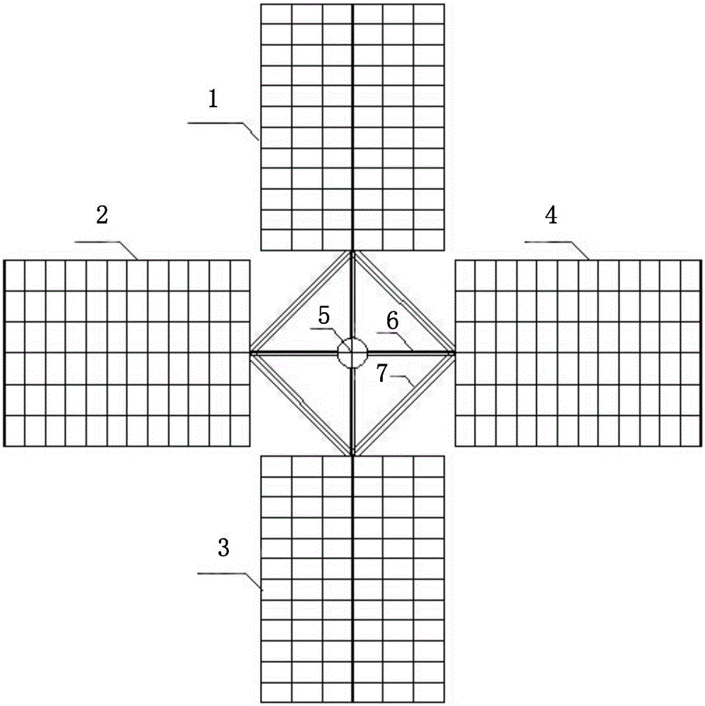
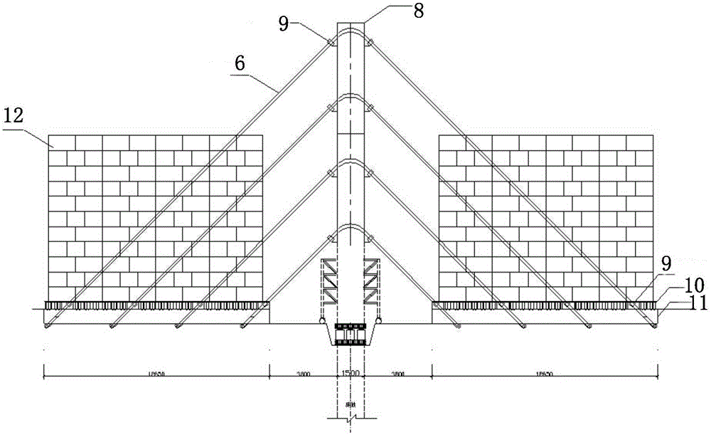
[0028] Figure 2-10 Shown is the counter force device of the super large tonnage ballast platform provided by the present invention, the counter force device includes a main tower 8, a stacked ballast platform, an anti-slip cross brace 7, several quick connectors 9, several counterweights 12 and Stay cables 6, the stacking and weighting platform is arranged around the main tower 8 at the center of the main tower 8, and the two ends of the anti-slip cross brace 7 respectively support the main beam of the stacking and weighing platform 11, the two ends of the stay cables 6 are respectively connected to the stacking weight platform and the main tower 8 through the quick connectors 9 in turn, and several counterweights 12 are evenly arranged on the Stacked on the weight platform. The tonnage can be increased by stacking and stacking, and the tonnage is highly expandable; the requirements for the bearing capacity of the foundation are low; the stability and safety of the platform ...


PUM

PropertyMeasurementUnit
Lengthaaaaaaaaaa
Heightaaaaaaaaaa
Widthaaaaaaaaaa

Abstract

The invention relates to a counter-force device for a super tonnage blasting platform. The counter-force device comprises a sub-stack blasting platform which is of a cross shape, wherein an intersection of the cross is coincided with the central point of a main tower; the beam ends of main beams of the sub-stack blasting platform are respectively supported by two ends of non-slip cross arms, two ends of stay cables are sequentially and respectively connected with the sub-stack blasting platform and the main tower by virtue of quick connectors, and a plurality of balancing weights are respectively and uniformly arranged on the sub-stack blasting platform. The counter-force device has the beneficial effects that the tonnage can be increased by virtue of each sub-stack, and the expansibility of the tonnage is high; requirements on bearing capacity of foundation soil are low; the platform is high in stability and security; the balancing weights are convenient to mount, each sub-stack can be independently mounted, and a working plane has multiple points, so that the mounting progress is facilitated; the working environment is safe, and detectors do not need to work in a bottom passage of the platform, so that the security of the working environment for personnel is greatly improved; the unit-tonnage construction cost of the platform is low, and each component of the platform is small in size and low in weight, so that the lifting and the transportation are facilitated, the utilization rate of the load weight is high, and the transportation and lifting costs of buttresses can be saved.

Description

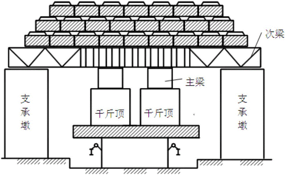
technical field [0001] The invention relates to the technical field of detection of construction engineering foundation piles, in particular to a device for providing reaction force for the vertical bearing capacity test of a single pile in the detection of foundation piles of construction engineering. Background technique [0002] In the foundation pile detection of construction engineering, the ballast platform reaction device is a commonly used loading reaction device for the vertical bearing capacity test of a single pile. The tonnage of the ballast platform reaction device directly determines the size of the test loading value. At present, the commonly used ballast platform reaction device is composed of supporting pier, main beam, secondary beam, counterweight, etc. The center point of the pile is taken as the center of the platform on site, and the ballast platform is built above the foundation pile, such as figure 1 shown. The load transfer path is as follows: the m...

Claims


Application Information

Patent Timeline
IPC IPC(8): E02D33/00
Inventor 林春伟程秉坤傅根根
Owner 林春伟
Learn More