Landing leg locking device and engineering machinery with same

A technology of locking outriggers and locking plates, which is applied in transportation and packaging, vehicle maintenance, lifting vehicle accessories, etc., and can solve problems such as cumbersome operation and poor reliability

Active Publication Date: 2015-12-09
XIAMEN XGMA MACHINERY
View PDF11 Cites 2 Cited by
  • Summary
  • Abstract
  • Description
  • Claims
  • Application Information

AI Technical Summary

Problems solved by technology

[0002] Traditional construction machinery such as concrete pump trucks and wheeled cranes need to install locks on the outriggers in order to prevent the outriggers from swinging or stretching out accidentally when they are retracted, and to improve their safety and stability during driving. The device fixes it on the frame. The outrigger locking device requires the structure to be as simple as possible, easy to operate, and reliable in locking. The existing outrigger locking device is generally a locking device composed of a pin shaft, a pin seat and a fixed iron chain. The operation is cumbersome and the reliability is poor

Method used


Image

  • Landing leg locking device and engineering machinery with same
  • Landing leg locking device and engineering machinery with same
  • Landing leg locking device and engineering machinery with same

Examples


Embodiment 1

[0031] like figure 1 , figure 2 As shown, a locking device for outriggers includes a limit shaft 1, an upper round tube 2, a lower round tube 3 and a spring 4, and the upper round tube 2 and the lower round tube 3 respectively have oblique Cutting surfaces 21, 31, the angle α between the oblique cutting surface and the horizontal plane is 30°-60°, the oblique cutting surface of the upper round pipe and the oblique cutting surface of the lower round pipe are respectively provided with positioning surfaces 211, 311, the above two There is an included angle between the positioning surfaces in the initial state, that is, when the oblique cutting surfaces 21, 31 of the upper round tube 2 and the lower round tube 3 need to be rotated by a certain angle to match the respective positioning surfaces 211, 311 with each other, the range of the included angle can be Adjust according to actual needs, the included angle between the two positioning surfaces in this embodiment is 90°, and a...

Embodiment 2

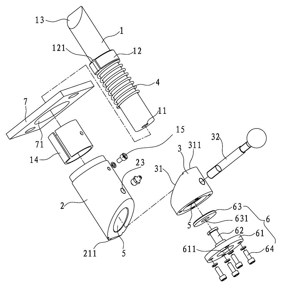
[0036] like image 3 , Figure 4As shown, the present invention also provides a more optimized outrigger locking device, the structure of which is basically the same as that of Embodiment 1, but the structure at the top of the limiting shaft, the matching structure between the positioning block and the upper round tube, and the limiting There is a difference in the positioning assembly between the bottom of the shaft and the lower round pipe, specifically: a bevel 13 is provided on the top of the limit shaft 1, and the bevel 13 is aligned with the bevel of the stop block 8 installed on the swing leg of the pump truck. The slope of the mouth is consistent to ensure that the two can cooperate with each other when they are in contact with each other; a longitudinal flange 121 is provided on the positioning block 12 of the limit shaft 1, and a chute is provided on the inner wall of the upper circular tube 2 (Fig. not shown) or by fixing a directional tube 14 with a chute by bolts...


PUM


Abstract

The invention discloses a landing leg locking device and engineering machinery with the same. The landing leg locking device comprises a limiting shaft, an upper circular tube, a lower circular tube and a spring, the upper circular tube and the lower circular tube are each provided with a slant tangent plane, the slant tangent planes are mutually matched, the slant tangent plane of the upper circular tube and the slant tangent plane of the lower circular tube are each provided with a locating surface, an included angle exists between the two locating surfaces in an initial state, and meanwhile a through hole formed in the middle of the upper circular tube is communicated with a through hole formed in the middle of the lower circular tube; the limiting shaft is rotatably arranged in the through hole of the upper circular tube and the through hole of the lower circular tube in a penetrating mode, the top of the limiting shaft can extend out of the upper circular tube, and the bottom of the limiting shaft abuts against a locating component which is arranged at the bottom of the lower circular tube; the spring is arranged on the limiting shaft in a sleeving mode and internally arranged in the through hole of the upper circular tube or the through hole of the lower circular tube; the lower circular tube is driven to rotate along a slant cut relative to the upper circular tube, elastic deformation of the spring is overcome, the limiting shaft is driven to produce the up-and-down displacement, and therefore switching of the swinging landing leg locking state is achieved conveniently and rapidly.

Description

technical field [0001] The invention relates to the field of engineering machinery, in particular to an outrigger locking device and an engineering machine with the outrigger locking device. Background technique [0002] Traditional construction machinery such as concrete pump trucks and wheeled cranes need to install locks on the outriggers in order to prevent the outriggers from swinging or stretching out accidentally when they are retracted, and to improve their safety and stability during driving. The device fixes it on the frame. The outrigger locking device requires the structure to be as simple as possible, easy to operate, and reliable in locking. The existing outrigger locking device is generally a locking device composed of a pin shaft, a pin seat and a fixed iron chain. Need personnel to get off its loaded down with trivial details operation, poor reliability. [0003] In view of this, the present inventor has conducted in-depth research on the above-mentioned de...

Claims


Application Information

Patent Timeline
Patent Type & Authority Applications(China)
IPC IPC(8): B60S9/02
CPCB60S9/02
Inventor 吕专真李良荣王少波郑伟
Owner XIAMEN XGMA MACHINERY
Why Eureka
Try Eureka