Electric vehicle management system
A technology for electric vehicles and management systems, applied in electric vehicles, power management, electric vehicle charging technology, etc.
- Summary
- Abstract
- Description
- Claims
- Application Information
AI Technical Summary
Problems solved by technology
Method used
Image

Examples
Embodiment approach 1
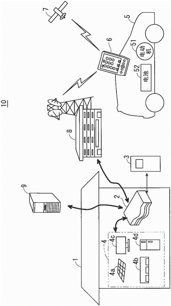
[0057] figure 1 It is a block diagram showing a schematic configuration of the electric vehicle management system 10 according to Embodiment 1 of the present invention. The electric vehicle management system 10 includes a demand household 1, an energy management system (EMS) 2, a charging and discharging device 3, home appliances 4, an electric vehicle 5, a portable terminal device 6, a base station device 8, and a server device 9, which will be described later. image 3 The communication line 20 shown is constituted.
[0058] The EMS 2 , the charging and discharging device 3 and the home appliance 4 are installed in the demanded household 1 . The home appliance 4 includes, for example, a solar power generation (abbreviation: PV) device 4a, an air conditioner (hereinafter referred to as "air conditioner") 4b, AV (AudioVisual: audio-visual) equipment 4c, and a refrigerator 4d. The electric vehicle 5 includes a motor 51 and a battery 52 . The base station device 8 is installe...
Embodiment approach 2
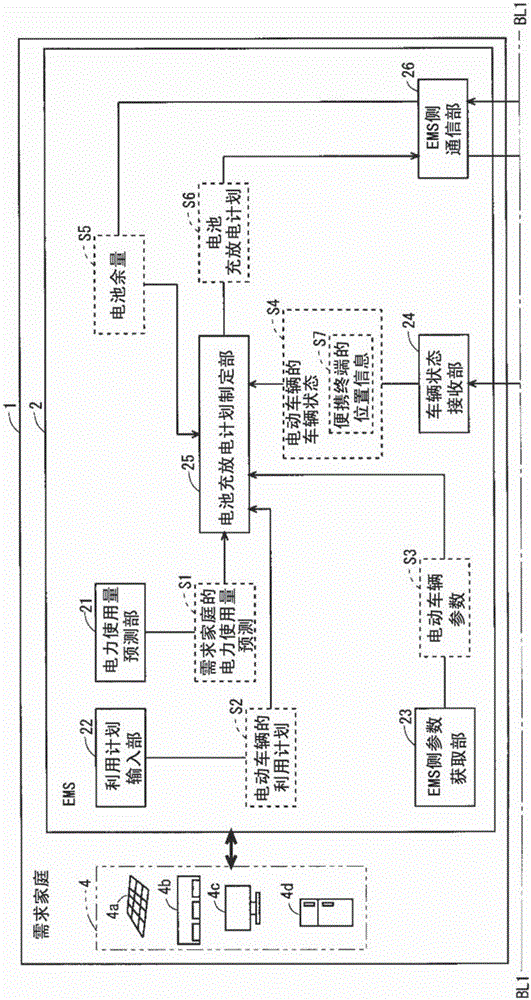
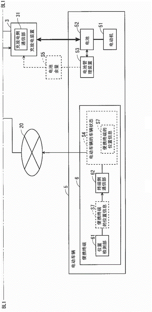
[0154] Figure 10 and Figure 11 It is a block diagram showing the configurations of the demand household 1 , the EMS 2 , the electric vehicle 5 , and the portable terminal 6 in the electric vehicle management system according to Embodiment 2 of the present invention. Figure 10 and Figure 11 They are connected at the position of the boundary line BL2. The electric vehicle management system of the present embodiment is similar in structure to the electric vehicle management system 10 of the first embodiment described above, so the same reference numerals are attached to the same structures, and common descriptions are omitted. In the following description, the electric vehicle management system according to the present embodiment is denoted by reference numeral "10A".
[0155] The electric vehicle management system 10A of the present embodiment is configured to include: a demand household 1 , an EMS 2 , a charge / discharge device 3 , a home appliance 4 , an electric vehicle...
Embodiment approach 3
[0226] Figure 16 and Figure 17 It is a block diagram showing the configurations of the demand household 1 , the EMS 2 , the electric vehicle 5 , and the portable terminal 6 in the electric vehicle management system according to Embodiment 3 of the present invention. Figure 16 and Figure 17 They are connected at the position of the boundary line BL3. The electric vehicle management system of the present embodiment is similar in structure to the electric vehicle management system 10 of the first embodiment described above, so the same reference numerals are attached to the same structures, and common descriptions are omitted. In the following description, the electric vehicle management system according to the present embodiment is denoted by attaching a reference numeral "10B".
[0227] The electric vehicle management system 10B of the present embodiment is configured to include: a demand household 1 , an EMS 2 , a charging / discharging device 3 , a home appliance 4 , an ...
PUM
 Abstract
Description
Claims
Application Information
 - R&D
- Intellectual Property
- Life Sciences
- Materials
- Tech Scout
- Unparalleled Data Quality
- Higher Quality Content
- 60% Fewer Hallucinations
Browse by: Latest US Patents, China's latest patents, Technical Efficacy Thesaurus, Application Domain, Technology Topic, Popular Technical Reports.
© 2025 PatSnap. All rights reserved.Legal|Privacy policy|Modern Slavery Act Transparency Statement|Sitemap|About US| Contact US: help@patsnap.com