Constant velocity joint

A universal joint, circumferential direction technology, used in elastic couplings, couplings, mechanical equipment, etc., can solve problems such as increasing the friction of universal joints, reduce friction surface and friction power, simple cost, Weight saving and compact effect

Inactive Publication Date: 2015-12-02
VOLKSWAGEN AG
View PDF12 Cites 0 Cited by
  • Summary
  • Abstract
  • Description
  • Claims
  • Application Information

AI Technical Summary

Problems solved by technology

In this connection, document WO 01 / 61203 A2 describes the guiding of the retaining ring not only at the joint outer part but also at the joint inner part by spherical contact surfaces, which however increases the friction in the joint

Method used


Image

  • Constant velocity joint
  • Constant velocity joint
  • Constant velocity joint

Examples


Embodiment Construction

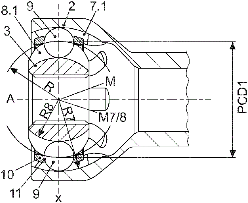
[0034] The exemplary embodiment shows a synchronous joint 1 with two joint components, a joint outer part 2 and a joint inner part 3 .

[0035] The joint inner part 3 is arranged in the bell-shaped outer joint part 2 and has an internal toothing for a coupling shaft or the like.

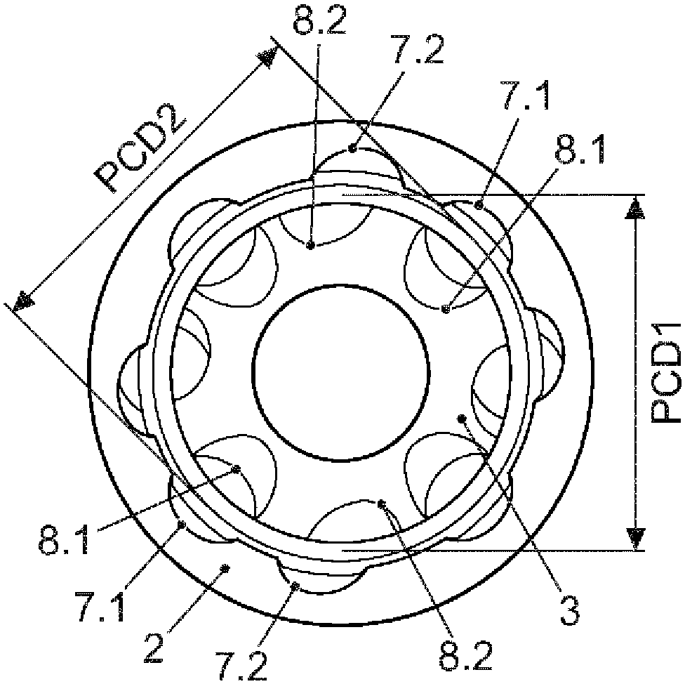
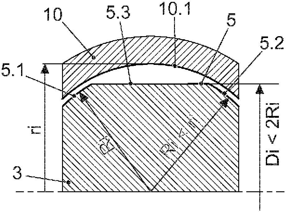
[0036]On the inner circumference 4 of the joint outer part 2 and on the outer circumference 5 of the joint inner part 3 respectively a large number of, for example eight or sixteen ball raceways 7 and 8 are formed, which are formed accordingly. facing each other. The ball raceway 7 on the joint outer part 2 and the ball raceway 8 on the joint inner part 3 respectively form a ball raceway pair. Balls 9 are respectively accommodated in each ball raceway pair.

[0037] Furthermore, a retaining ring 10 is arranged between the joint outer part 2 and the joint inner part 3 , which retainer has a plurality of windows 11 at its periphery. Balls 9 are arranged in each of these windows 11 , which are held i...


PUM


Abstract

The invention relates to a constant velocity joint, comprising a joint outside part (2) having ball tracks (7) on the inside circumference (4), a joint inside part (3) having ball tracks (8) on the outside circumference (5), wherein a ball track (7) on the joint outside part (2) and a ball track (8) on the joint inside part (3) form a ball track pair, one ball (9) per ball track pair and a cage (10) which is arranged between the joint outside part (2) and the joint inside part (3) and has windows (11) in which the balls (9) are received. According to the invention, a first group of ball track pairs, having ball tracks (7.1, 8.1) which are curved and extend in a radial plane encompassing the center axis (A) of the respective joint component, and a second group of ball track pairs, having ball tracks (7.2, 8.2) which extend straight and cross each other, are thus formed. The cage (10) is loosely guided on one of the two jointed components (2, 3) and spaced apart from the other jointed component (3, 2). This results in a particularly lightweight constant velocity joint which is simple and cost-effective to produce, having particularly high efficiency and particularly low interior friction.

Description

technical field [0001] The invention relates to a synchronous universal joint (Gleichlaufgelenk, sometimes called a constant velocity joint), comprising: an outer part of the joint with a ball raceway (Kugellaufbahn) at the inner periphery; The universal joint inner part of the ball raceway, wherein the ball raceway at the universal joint outer part and the ball raceway at the universal joint inner part respectively form a ball raceway pair; for each ball raceway pair respectively a ball; and a retainer (Käfig, sometimes called a cage) disposed between the outer gimbal and the inner gimbal and having a window in which the ball is received. Background technique [0002] So-called ball cage joints (Rzeppagelenk, sometimes called Erzebo joints) - for example in the form of UF / RF - are often used as synchronous fixed joints on the wheel side on the front axle axle of motor vehicles (Vorderachsseitenwelle), the ball raceway of the cage joint extends in a radial plane containing ...

Claims


Application Information

Patent Timeline
Patent Type & Authority Applications(China)
IPC IPC(8): F16D3/223F16D3/224F16D3/227
CPCF16D3/223F16D3/224F16D3/227F16D2003/22309
Inventor D.吉塔特冈萨莱斯G.沙夫M.拉贝M.乌勒
Owner VOLKSWAGEN AG
Why Eureka
Try Eureka