
Automatic sunlight tracking system of solar cell panel

A solar panel and automatic tracking technology, which is applied in the field of solar energy, can solve the problems of affecting the power generation efficiency of solar panels, weakening the light sensitivity of photosensitive elements, and high cost of solar tracking devices, and achieves high tracking accuracy, easy implementation, and improved power generation efficiency. Effect

Inactive Publication Date: 2015-12-02
GUILIN UNIV OF ELECTRONIC TECH
View PDF7 Cites 21 Cited by
  • Summary
  • Abstract
  • Description
  • Claims
  • Application Information

AI Technical Summary

Problems solved by technology

[0005] The existing timing tracking methods mainly include the detection of sunlight intelligent judgment tracking method, which uses photosensitive devices to sense the position of sunlight. Although the design is easy, due to the scattering of sunlight, the photosensitive devices are not sensitive to the deviation of the sunlight angle; Complicated weather will cause misjudgment, and the covering of dust will also weaken the light-sensing ability of the photosensitive element; at the same time, the harsh outdoor environment will also have a great impact on the accuracy and life of the photosensitive element, which will eventually affect the tracking effect
At the same time, the cost of this sun-tracking device is too high, which is not conducive to popularization.
[0006] In addition, changing climate and environmental conditions, such as rain, snow, frost and dust, also affect the power generation efficiency of solar panels

Method used


Image

  • Automatic sunlight tracking system of solar cell panel
  • Automatic sunlight tracking system of solar cell panel
  • Automatic sunlight tracking system of solar cell panel

Examples


Embodiment Construction

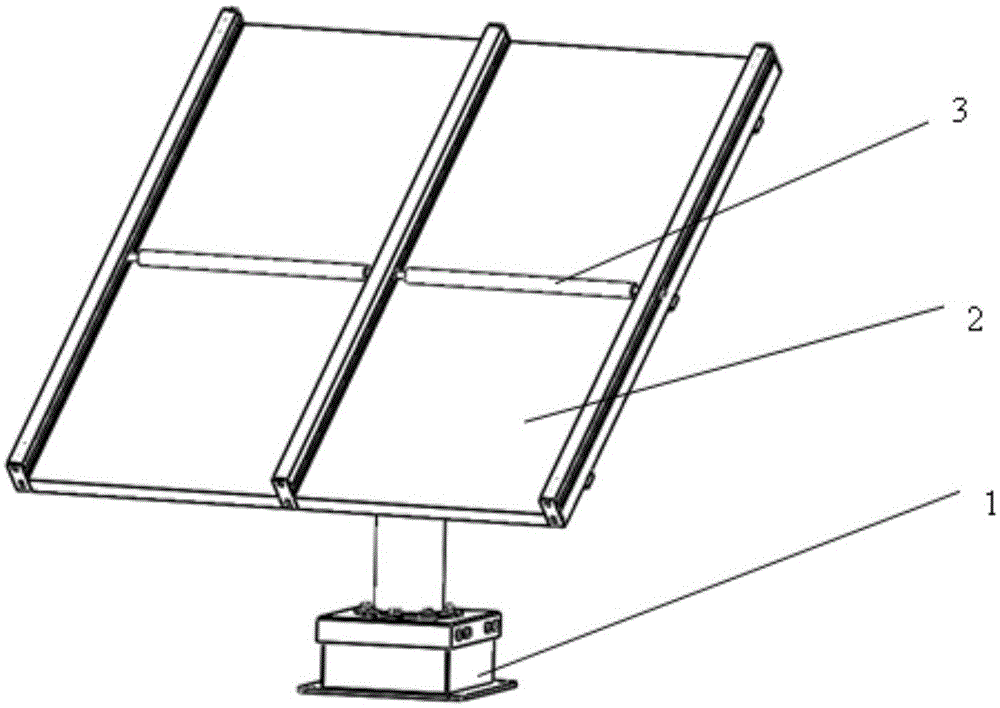
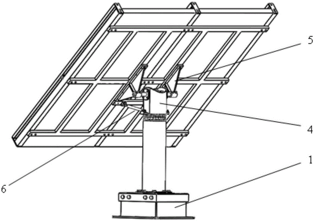
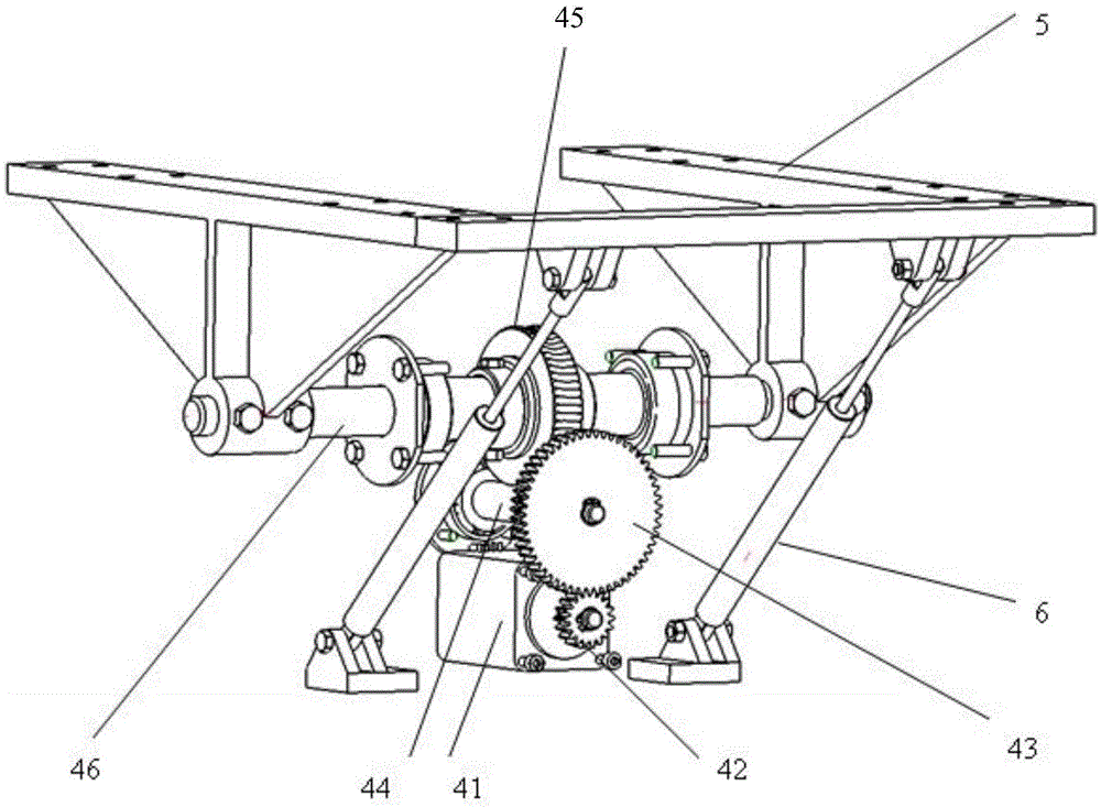
[0032] The overall appearance of the embodiment of the solar panel sunlight automatic tracking system is as follows: figure 1 and 2 As shown, the connection structure of the height angle tracking drive motor 41, the upper deceleration transmission mechanism and the height angle rotation shaft 46 is as follows image 3As shown; the azimuth tracking drive motor 11, the lower deceleration transmission mechanism and the azimuth rotation shaft 16 connection structure are as follows Figure 4 shown.

[0033] The azimuth tracking drive motor 11 and the upper deceleration transmission mechanism are installed in the lower box body 1, and the lower box body 1 is fixedly connected with the base. A vertical column casing 18 is installed on the lower box body 1, and the bottom end of the azimuth rotating shaft 16 is rotatably mounted on the base through a bearing and passes through the column casing 18. The altitude rotation shaft 46 is rotatably mounted on the top end of the azimuth ro...


PUM


Abstract

The invention provides an automatic sunlight tracking system of a solar cell panel. A central processor is connected to a clock module, and is equipped with a program that controls the attitude of a solar cell panel according to the current time and the geographical direction of the system. Output signals of the central processor access an elevation angle tracking driving motor and an azimuth tracking driving motor. The two motors are connected to and drive an elevation angle rotary shaft and an azimuth rotary shaft through an upper deceleration transmission mechanism and a lower deceleration transmission mechanism respectively. The elevation angle rotary shaft is disposed on the azimuth rotary shaft. A solar cell panel support is fixed to the elevation angle rotary shaft. The bottom of the support is provided with air springs to have stabilizing and supporting effects and to resist wind. The upper and lower worm shafts of the transmission mechanisms are self-locking worms. The solar cell panel is provided with a dust collector having dust removing rollers, and the dust removing rollers roll on the cell panel and remove dust by means of the gravity. The system is also provided with a lightning protection apparatus. All parts are equipped with antirust processing layers. The system does not need a sensor. The cell panel is made to keep facing a sunlight incident direction according to the azimuth of the sun. The power generation efficiency is improved. The system is high in tracking precision, simple in structure and low in cost.

Description

technical field [0001] The invention relates to the technical field of solar energy, in particular to a solar panel sunlight automatic tracking system. Background technique [0002] With the rapid consumption of non-renewable resources in the world, the utilization of solar energy resources has attracted much attention. Solar photovoltaic power generation devices are an important way of utilizing solar energy resources, and their development prospects are very broad. [0003] Most of the solar panels of solar panel power generation devices on the market are installed at fixed positions and fixed angles, so the angle at which they receive sunlight is also fixed. However, due to the rotation and revolution of the earth itself, the incident angle of the sun's rays on the solar panel varies with latitude, season and time of day. Fixed-angle solar panels cannot track the changing sun's rays, that is, they cannot fully utilize solar energy and its photoelectric conversion benefit...

Claims


Application Information

Patent Timeline
IPC IPC(8): G05D3/10H02S20/32
CPCY02E10/50
Inventor 李雪梅廖新拢钟元鑫陈冠明吴林礼
Owner GUILIN UNIV OF ELECTRONIC TECH
Learn More