
A camping oil heating stove

A heating furnace and oil-fired hearth technology, which is applied in the heating field, can solve the problems that affect field workers' night rest, generator noise is loud, and combustion is incomplete, so as to shorten the chemical reaction time, increase the thermal load limit, and reduce the heat of combustion loss effect

Active Publication Date: 2017-10-13
中国人民解放军32181部队
View PDF5 Cites 0 Cited by
  • Summary
  • Abstract
  • Description
  • Claims
  • Application Information

AI Technical Summary

Problems solved by technology

[0002] At present, when camping in the wild for heating, coal firewood heating stoves are mainly used in living tents. The stove uses coal, firewood, dry animal manure, etc. as fuel. When used in plateau areas, there are problems of incomplete combustion, serious heat supply attenuation, short fire closure time, and even continuous combustion cannot be maintained.
In addition, coal-fired heating stoves need to add solid fuels such as coal, firewood, and dry animal manure at intervals of 2 to 3 hours, and personnel are required to be on duty when used at night
For tents with a large indoor area, plateau heating is mainly solved by plateau fuel heaters. However, the heater needs an external power supply when it is running, and it needs to be equipped with a generator with a certain power when it is used in the field. The noise of the generator is relatively loud, which affects field work. night rest
In addition, when the generator is maintained or fails, the heater is also forced to stop and stop heating
For tents with a small area and fewer occupants, the use of fuel oil heaters for heating has problems such as high investment costs and high operating costs.
Therefore, the problem of heating small area tents in plateau areas has not been well solved for many years.

Method used


Image

  • A camping oil heating stove
  • A camping oil heating stove

Examples


Embodiment Construction

[0023] The present invention will be described in further detail below in conjunction with the accompanying drawings.

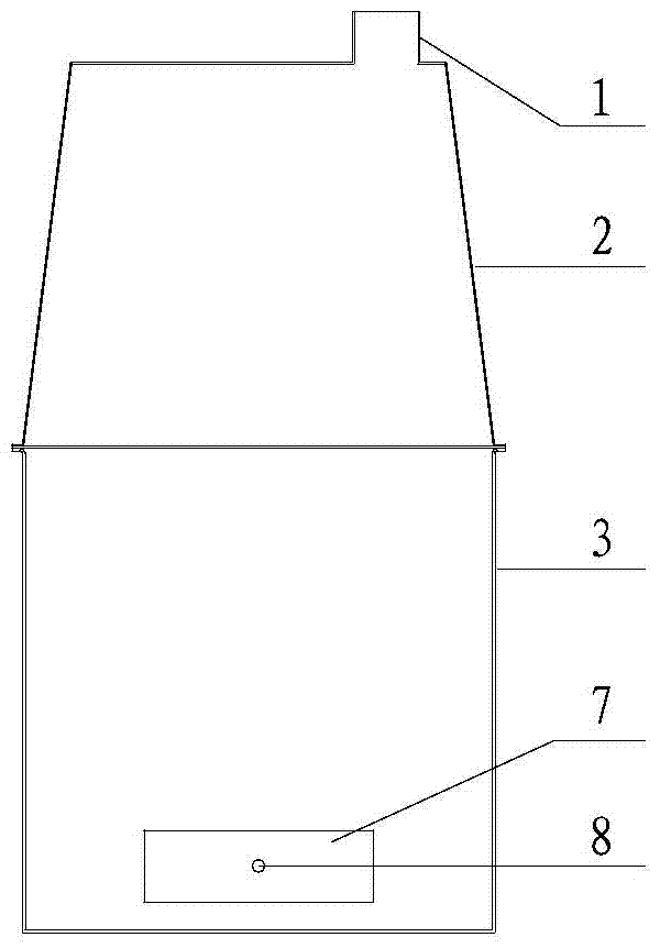
[0024] Such as figure 1 with 2 As shown, the present invention comprises body of heater 3, is provided with fuel burner hearth 4 in the body of heater 3, is provided with some air inlet holes 10 on the wall surface of fuel oil furnace hearth 4, and the diameter of air inlet hole 10 is 1.5~5mm, and some air inlet holes 10 The total area accounts for 0.1~1% of the surface area of ​​the fuel furnace 4 barrels.

[0025] The fuel furnace 4 is provided with a vaporization device for evaporating fuel; specifically, the vaporization device is fixed in the fuel furnace 4 through a steady flow plate. The steady flow plate includes an upper steady flow plate 5 and a lower steady flow plate 6 , and the overheating pipe includes a lower end of the overheating pipe arranged below the lower steady flow plate 6 .

[0026] Vaporization device comprises vaporization cap 12,...


PUM


Abstract

A camping oil-fired heating stove, comprising a furnace body, the furnace body is provided with an oil-fired furnace, a number of air inlet holes are opened on the wall of the oil-fired furnace, a vaporization device for evaporating and vaporizing the fuel is arranged in the fuel-fired furnace, and the upper part of the fuel-fired furnace A fire gathering cover is provided; an air inlet is provided at the lower part of the furnace body, a conical heat radiation cylinder is provided on the top of the furnace body, and a chimney seat is provided on the top of the conical heat radiation cylinder. The present invention adopts a vaporization device to realize fuel vaporization-combustion self-sustaining and non-powered combustion. At the same time, relying on the suction of the chimney during combustion, the combustion-supporting air is sucked in from the bottom air inlet, and the furnace body and the conical heat radiation tube are under negative pressure, which effectively reduces indoor pollutant emissions. The invention does not require personnel to be on duty at night, and is a camping fuel oil heating stove with high combustion efficiency, safety and no pollution.

Description

technical field [0001] The invention belongs to the technical field of heating, and in particular relates to a camping oil heating stove. Background technique [0002] At present, when camping in the wild for heating, coal firewood heating stoves are mainly used in living tents. The stove uses coal, firewood, dry animal manure, etc. as fuel. When used in plateau areas, there are problems of incomplete combustion, severe heat supply attenuation, short fire closure time, and even continuous combustion cannot be maintained. In addition, coal-fired heating stoves need to be filled with solid fuels such as coal, firewood, and dry animal manure at intervals of 2 to 3 hours, and personnel are required to be on duty when used at night. For tents with a large indoor area, plateau heating is mainly solved by plateau fuel heaters. However, the heater needs an external power supply when it is running, and it needs to be equipped with a generator with a certain power when it is used in ...

Claims


Application Information

Patent Timeline
Patent Type & Authority Patents(China)
IPC IPC(8): F24C5/20F24C15/24F23D11/00F23D11/44F23D11/36
Inventor 高怀斌李洪峻黄光宏李俊
Owner 中国人民解放军32181部队
Learn More