Glass double face synchronous cutter

A cutter, double-sided technology, applied in glass cutting devices, glass manufacturing equipment, manufacturing tools, etc., can solve the problems of inaccurate correspondence, glass cannot be completely cracked, glass crushing, etc., and achieve accurate cutting effect.

Active Publication Date: 2015-12-02
太仓市大烨建筑工程有限公司
View PDF6 Cites 0 Cited by
  • Summary
  • Abstract
  • Description
  • Claims
  • Application Information

AI Technical Summary

Problems solved by technology

[0002] Tempered glass is a kind of safety glass, which has the advantages of high strength and safe use. However, cutting and processing the glass after tempering will easily lead to glass shattering. Therefore, the glass must be cut to the corresponding size before tempering.
[0003] At present, when cutting the glass in a circle, it is usually to draw a circular mark along the cutting track on one surface of the glass, and then apply a light force along the scratch, and the glass will crack along the circular mark to realize the cutting; However, for thicker glass, the glass cannot be completely cracked by this method of single-sided scratching, and circular cutting cannot be achieved. The current method is to scratch the glass on both sides of the glass circle mark, and then move
However, at present, these two scratches are usually performed separately, and the defect of the separate process is that the positions of the two scratches usually cannot be accurately corresponded, but are staggered from each other, and the staggering will cause the cracks on both sides of the glass to also Staggered each other, when the glass cracks along the circular marks on both sides of the surface, the cracks will be inclined, that is, the cutting edge of the glass is inclined, the cutting size is inaccurate, or it will directly cause the glass to crack at different places on the two sides of the surface. open and damaged

Method used


Image

  • Glass double face synchronous cutter
  • Glass double face synchronous cutter

Examples


Embodiment Construction

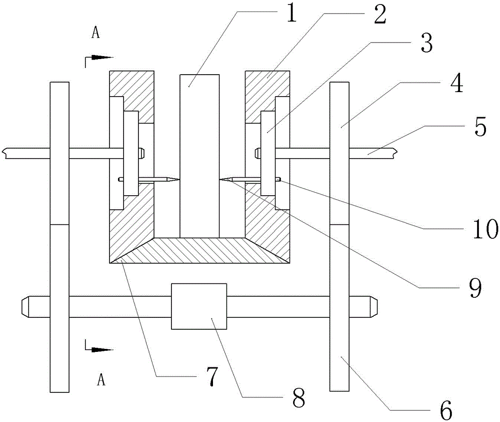
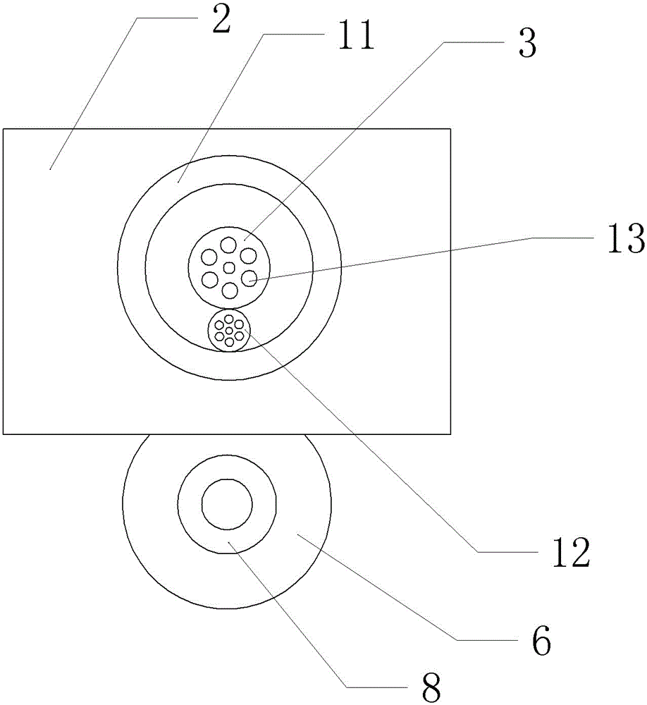
[0017] Among them: glass 1, side plate 2, sun gear 3, driven gear 4, main shaft 5, driving gear 6, bottom plate 7, motor 8, blade 9, split shaft 10, first through hole 11, planetary gear 12, second Through hole 13.

[0018] Such as figure 1 , figure 2 As shown, the glass double-sided synchronous circular cutter of the present invention includes a "U"-shaped plate and two main shafts 5, the "U"-shaped plate includes two side plates 2 and a bottom plate 7, and the cross-section of the bottom plate 7 is inverted " V-shaped, two side plates 2 are symmetrically arranged on both sides of the bottom plate 7, and the “U”-shaped plate is placed vertically. Both side plates 2 of the “U”-shaped plate are provided with a first through hole 11. The first through-hole The hole 11 is a stepped hole, and the inner diameter of the stepped hole increases sequentially from the inside to the outside; the first through hole 11 is provided with a ring gear, and the ring gear is connected to the ...


PUM


Abstract

The invention discloses a glass double face synchronous cutter comprising a U-shaped board and two main shafts sleeved with sun gears, wherein two side plates of the U-shaped board are provided with first through holes provided with tooth rings, and the two sun gears are positioned at the center of the two tooth rings. Planetary gears engaged with the sun gears and the tooth rings are positioned between the sun gears and the tooth rings, and split shafts provided with blades at the inner ends are positioned at the center of the planetary gears. The two sun gears, two planetary gears and two tooth rings axisymmetrically distribute along the center line of the U-shaped board, and a drive unit driving the two main shafts to rotate synchronously is positioned between the two main shafts. The invention provides the glass double face synchronous circle cutter which can scratch round marks synchronously at the position corresponding to the two side surfaces of the glass and circularly cut the glass.

Description

technical field [0001] The invention belongs to the field of glass processing, in particular to a glass double-sided synchronous circular cutter. Background technique [0002] Tempered glass is a kind of safety glass, which has the advantages of high strength and safe use. However, cutting and processing the glass after tempering will easily lead to glass shattering. Therefore, the glass must be cut to the corresponding size before tempering. [0003] At present, when cutting the glass in a circle, it is usually to draw a circular mark along the cutting track on one surface of the glass, and then apply a light force along the scratch, and the glass will crack along the circular mark to realize the cutting; However, for thicker glass, the glass cannot be completely cracked by this method of single-sided scratching, and circular cutting cannot be achieved. The current method is to scratch the glass on both sides of the glass Round marks, and then move. However, at present, t...

Claims


Application Information

Patent Timeline
Patent Type & Authority Applications(China)
IPC IPC(8): C03B33/02
Inventor 韩国才
Owner 太仓市大烨建筑工程有限公司
Why Eureka
Try Eureka