Barrel stretch forming process and barrel manufactured by process
A technology for drawing and forming barrels, applied in the field of barrel bodies, can solve the problems of requiring large supporting equipment, unfavorable polishing treatment, and consuming human resources, etc., and achieves the effect of reducing processing procedures, smooth outer surface, and uniform feeding.
- Summary
- Abstract
- Description
- Claims
- Application Information
AI Technical Summary
Problems solved by technology
Method used
Image
Examples
Embodiment 1
[0026] A barrel stretch forming process, comprising:
[0027] Step 1, provide round material;
[0028] Step 2: Carry out one forward stretching and one reverse stretching successively on the circular material successively.
[0029] After the forward stretching is completed, the first forming barrel is obtained, and after the reverse stretching is completed, the second forming barrel is obtained, wherein the depth of the second forming barrel is greater than the depth of the first forming barrel, and the second forming barrel The diameter of the body is smaller than the diameter of the initial molding barrel.
[0030] After the reverse stretching is completed, the second molding barrel has a skirt, and the skirt is cut and a part of the edge is reserved, and the reserved part of the edge is crimped.
[0031] Before the skirt is cut, the second forming barrel body is subjected to a bottom pressing process so that the second forming barrel body has a barrel bottom of a preset s...
Embodiment 2
[0034] A barrel body, which is made by the process described in the first embodiment, makes the outer surface of the barrel body smooth without polishing treatment, and no stretch mark or bubbling phenomenon occurs.
Embodiment 3
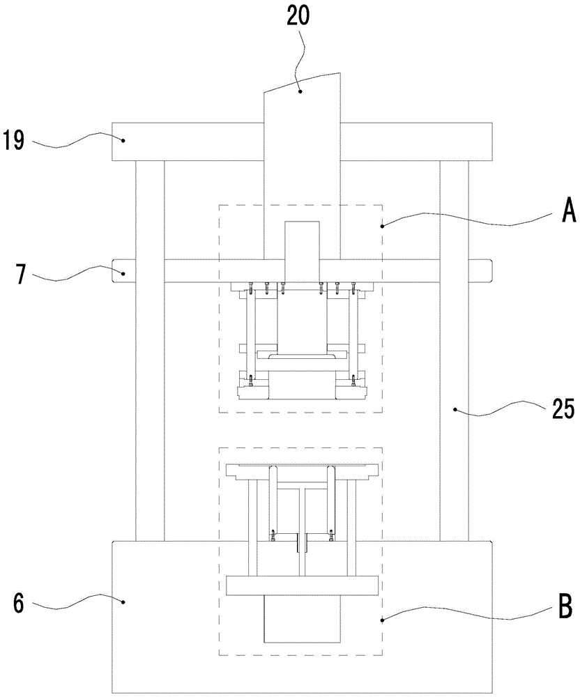
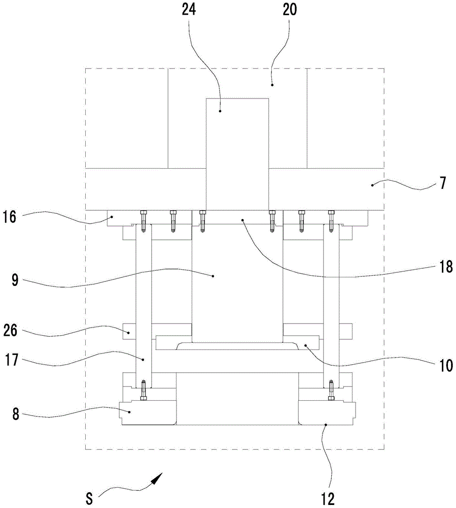
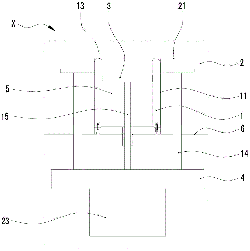
[0036] Such as Figure 1 to Figure 15 As shown, a positive and negative stretching composite mold is used to make a round material 22 (ie blank) into a barrel, including an upper mold S and a lower mold X;
[0037] The lower mold X includes a working table surface 6 and a concave-convex mold 1, a lower pressing ring 2, a lower mold ejection plate 3 and a lower power movement plate 4 arranged on the working table surface, and the lower pressing material ring 2 is set on the concave-convex mold 1, the lower mold ejector plate 3 is located inside the concave-convex mold 5, and the lower power movement plate 4 is connected with the lower press ring 2 and the lower die ejector plate 3 respectively, so that the lower press ring 2 and the lower die ejector plate 3 are connected. The ejector plate 3 of the lower mold moves along the axial direction of the concave-convex mold 1 under the push of the lower power movement plate 4, and the concave-convex mold 1 is fixed on the working tab...
PUM
 Abstract
Description
Claims
Application Information
 - R&D
- Intellectual Property
- Life Sciences
- Materials
- Tech Scout
- Unparalleled Data Quality
- Higher Quality Content
- 60% Fewer Hallucinations
Browse by: Latest US Patents, China's latest patents, Technical Efficacy Thesaurus, Application Domain, Technology Topic, Popular Technical Reports.
© 2025 PatSnap. All rights reserved.Legal|Privacy policy|Modern Slavery Act Transparency Statement|Sitemap|About US| Contact US: help@patsnap.com


