
Component surface pollutant composite cleaning device and method

A technology for cleaning devices and parts, which is applied in the direction of using liquid cleaning methods, cleaning methods and utensils, chemical instruments and methods, etc., which can solve the problems of harmful personnel, large consumption of dry ice, high cost, etc., to avoid damage, avoid Effects that cause damage and reduce negative effects

Inactive Publication Date: 2015-12-02
ACADEMY OF ARMORED FORCES ENG PLA
View PDF5 Cites 11 Cited by
  • Summary
  • Abstract
  • Description
  • Claims
  • Application Information

AI Technical Summary

Problems solved by technology

Chemical cleaning usually uses chemical reagents, and the waste liquid generated during the cleaning process and after cleaning is harmful to personnel and pollutes the environment; although pyrolysis cleaning technology can heat and decompose heavy oil stains on the surface and interior of parts to achieve surface cleaning, it is more suitable for high melting point zero Parts, for parts with low melting point or parts that are easy to oxidize, the high temperature heating process will cause deformation and oxidation of the parts, and even change the heat treatment state of the parts; Effective cleaning cannot be achieved inside the structure and parts
[0006] It can be seen that none of the existing cleaning methods can effectively meet the high-efficiency, green, and low-cost remanufacturing cleaning requirements for heavy oil pollution on the surface of the aforementioned mechanical parts

Method used


Image

  • Component surface pollutant composite cleaning device and method
  • Component surface pollutant composite cleaning device and method
  • Component surface pollutant composite cleaning device and method

Examples


Embodiment 1

[0073] Please see Figure 4 , Figure 4 It is a flow chart of a specific embodiment of the compound cleaning method for surface pollutants of parts provided by the present invention.

[0074] The cleaning object in this embodiment is the heavy-duty Steyr diesel engine fuel injection pump parts with complex structure, various types and precision coordination, mainly including fuel injection pump casing, camshaft, plunger coupler, governor, etc. The inner and outer surfaces of these parts are attached to a large amount of heavy oil pollution, which is difficult to be effectively cleaned by conventional methods.

[0075] Step S11, put the parts to be cleaned into the tank of the water jet spraying system, and use a cleaning solution with a preset pressure and a preset temperature to clean the parts with water jets within a preset time.

[0076] (1) Liquid injection: Inject city water into the tank through the liquid inlet. The size of the tank is 1200mm×600mm×660mm. The volume ...

Embodiment 2

[0092] The cleaning object of this embodiment is the planetary reducer planetary frame of coal mining machinery equipment. Compared with the parts described in Embodiment 1, the surface grease and dirt of the planetary reducer planetary frame are relatively low, and the structure of the parts is relatively simple.

[0093] Step S21, put the parts to be cleaned into the tank of the water jet spraying system, and use a cleaning solution with a preset pressure and a preset temperature to clean the parts with water jets within a preset time.

[0094] (1) Liquid injection: Inject city water into the tank through the liquid inlet. The size of the tank is 1200mm×600mm×660mm. The volume of city water accounts for 90%-95% of the tank volume. Set the heating temperature at 50-55°C. Add 5 kilograms of sodium carbonate in the tank body, stir to make sodium carbonate dissolve completely.

[0095] (2) Loading: Put the hanging basket with the above parts to be cleaned through the conveying d...

Embodiment 3

[0110] The cleaning object in this embodiment is the concrete pump truck valve block with complex structure and serious surface oil pollution. Compared with the planet carrier of the planetary reducer described in Example 2, the grease and dirt on the surface of the valve block are also lower, but the structure of the parts is complex, with a large number of internal through holes and blind holes. In this embodiment, in view of the pollution state and structure of the inner and outer surfaces of the parts, the high-pressure and high-temperature water jet cleaning step is omitted, and ultrasonic precision cleaning and ultrasonic rinsing are directly performed.

[0111] Step S31, put the parts into the tank of the ultrasonic cleaning system, and use a cleaning solution with a preset temperature to perform ultrasonic cleaning on the parts within a preset time.

[0112] (1) Liquid injection: inject municipal water into the tank through the liquid inlet, the tank size is 1000mm×600...


PUM


Abstract

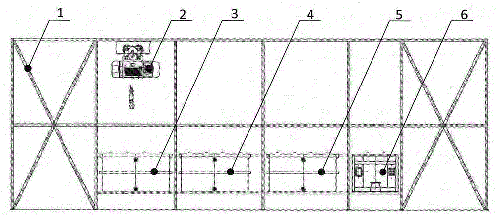
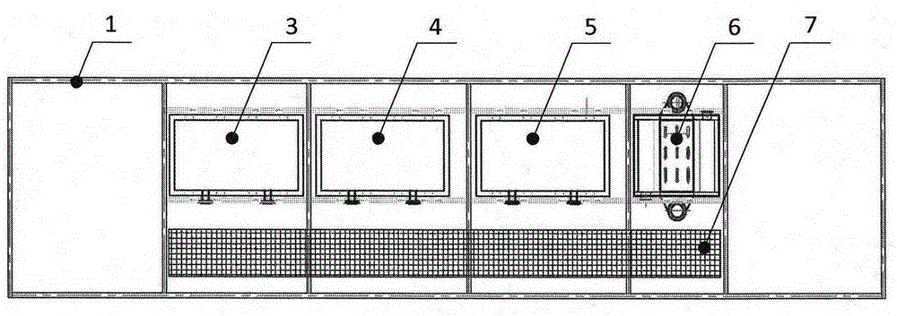
The invention relates to the re-production cleaning technical field, and especially relates to a component surface pollutant composite cleaning device and method; the component surface pollutant composite cleaning device comprises the following elements: a water jet spray cleaning system used for decomposition shedding treatment on component surface pollutant; an ultrasonic cleaning system used for doing ultrasonic cleaning on the component surface; an supersonic wave rinsing system used for doing supersonic wave rinsing for inner parts of the component; a blower drying system used for drying the parts after rinsing. The water jet spray cleaning system, the ultrasonic cleaning system, the supersonic wave rinsing system and the blower drying system are arranged in parallel in sequence on each work station of a frame; the component surface pollutant composite cleaning device also comprises a conveyer used for lifting and transferring hanging baskets between work stations, wherein the hanging basket is used for containing components.

Description

technical field [0001] The invention relates to the technical field of remanufacturing cleaning, in particular to a composite cleaning device for surface pollutants of parts that can be used for remanufacturing and cleaning of waste parts. The invention also relates to a compound cleaning method for surface pollutants of parts. Background technique [0002] Remanufacturing is different from the original manufacturing process. The cleaning technology is also an important process unique to the remanufacturing process and significantly different from the manufacturing process. It is important for ensuring the quality of remanufacturing products, reducing remanufacturing costs, and improving the life of remanufactured products. etc. are significant. Remanufacturing cleaning refers to the use of cleaning equipment or cleaning fluid to remove grease, rust, dirt, carbon deposits and other pollutants attached to the surface of waste parts by mechanical, physical, chemical or electr...

Claims


Application Information

Patent Timeline
Patent Type & Authority Applications(China)
IPC IPC(8): B08B7/04B08B3/02B08B3/12F26B21/00
CPCB08B3/02B08B3/12F26B21/00
Inventor 张伟于鹤龙汪勇宋占永吉小超魏世丞郭岗
Owner ACADEMY OF ARMORED FORCES ENG PLA
Learn More