
Gum-penetrating system of bioengineered teeth

A bioengineering and transgingival technology, applied in the field of transgingival systems for bioengineered teeth, can solve the problems of lack of periodontal ligament, implants vulnerable to trauma, time-consuming operation, etc., and achieve the effect of simplifying the surgical process

Active Publication Date: 2015-12-02
SICHUAN UNIV
View PDF5 Cites 1 Cited by
  • Summary
  • Abstract
  • Description
  • Claims
  • Application Information

AI Technical Summary

Problems solved by technology

However, in order to further realize the masticatory function, the crown must be restored by post-core crown, which means that the regenerated pulp tissue must be sacrificed, and pile driving, model preparation, and crown restoration must be performed, which is time-consuming and expensive. complicated operation
[0004] Moreover, dental implants only form osseointegration with the surrounding alveolar bone. Compared with natural teeth, osseointegrated implants do not have periodontal ligament. The lack of this important structure makes them feel the force and displacement. Relatively dull, the implant is vulnerable to trauma

Method used


Image

  • Gum-penetrating system of bioengineered teeth
  • Gum-penetrating system of bioengineered teeth
  • Gum-penetrating system of bioengineered teeth

Examples


Embodiment 1

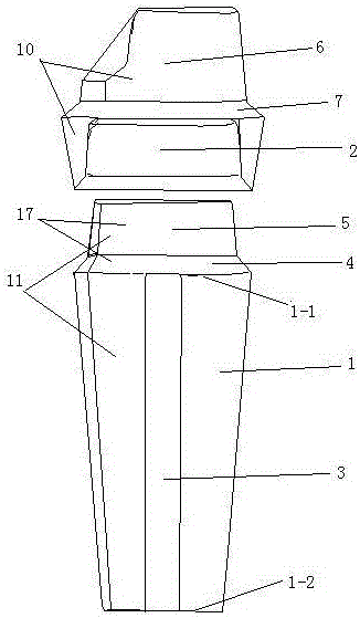
[0028] as attached figure 1 As shown, the design of the bioengineering gingival system includes a bioengineering dental bracket and a gingival abutment.

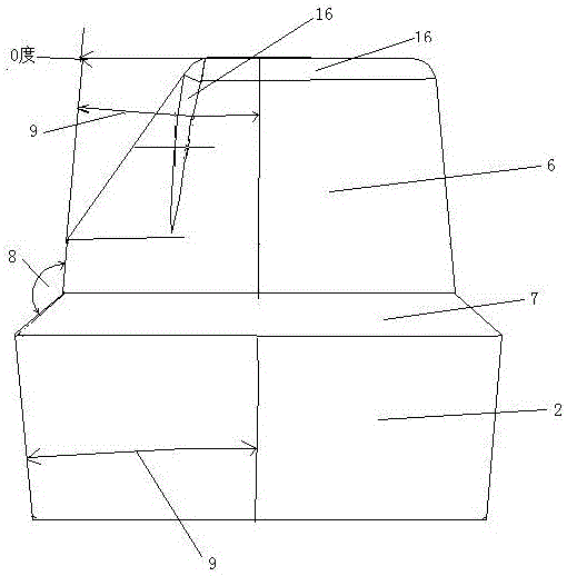
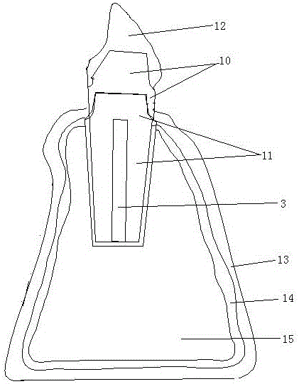
[0029] The lower part of the bioengineering tooth bracket is a bracket structure, and there is a hollow pulp cavity inside. The pulp cavity is conical, wide at the top and narrow at the bottom. It is also conducive to the injection of blood vessels and nerves, ensuring the nutrition of the pulp tissue itself and the regenerated dentin around the pulp cavity, making the texture of the regenerated dentin closer to natural teeth; the diameter of the pulp cavity is 1 / 3 of the diameter of the stent. The shape of the pulp chamber conforms to the shape of the outer frame, and each planar frame corresponds to the shape. The upper part of the bioengineering dental stent is a dental stent abutment with a closed design. There is a pre-prepared 135° dental stent obtuse angle shoulder at the neck of the dental stent abutment. The upper...

Embodiment 2

[0036] Others are as in embodiment 1, wherein the diameter of the pulp cavity is 1 / 2 of the diameter of the bracket, the obtuse angle of the obtuse angle shoulder of the tooth bracket or the obtuse angle shoulder of the crown edge is 130 °, the bonding part of the tooth bracket abutment and the crown are glued The cohesion angle of the knot is 4°.

Embodiment 3

[0038] Others are as in embodiment 1, wherein the diameter of the pulp cavity is 1 / 2.5 of the diameter of the bracket, the obtuse angle of the obtuse shoulder of the dental bracket or the obtuse angle of the crown edge shoulder is 140 °, the bonding part of the dental bracket abutment and the crown are glued The cohesion angle of the knot is 4.5°.


PUM


Abstract

The invention provides a gum-penetrating system of bioengineered teeth, comprising a bioengineered tooth stent and a gum-penetrating base. The bioengineered tooth stent comprises a stent body, a pulp cavity and a stent base; the pulp cavity is hollow and disposed in the stent body; upper and lower ends of the pulp cavity are connected with upper and lower ends of the stent body; the stent bae is provided with a stent obtuse shoulder and a stent base bonding portion; the stent base bonding portion is fixedly connected with the stent obtuse shoulder which is fixedly connected with the upper end of the stent body; the gum-penetrating base is provided with a crown bonding portion, a crown edge obtuse shoulder and a gum-penetrating base bonding portion; the crown bonding portion is integrally connected with the gum-penetrating base bonding portion through the crown edge obtuse shoulder; the stent obtuse shoulder and the stent base bonding portion are integrally connected with the gum-penetrating base by bonding. The system is good for regeneration of complete root including pulp tissues and periodontal tissues, and good basis is laid for final chewing ability and attractiveness of regenerated teeth.

Description

technical field [0001] The invention belongs to the field of oral regenerative medicine, in particular to a gingival system for bioengineered teeth. Background technique [0002] Bioengineered teeth, also known as cloning teeth or tooth tissue engineering (Tooth Tissue Engineering), refer to the tissue engineering means of obtaining whole teeth from single cells by means of in vitro and in vivo culture. Due to the similar structure of supporting tissues, "bioengineered teeth" should be more convenient to support fixed restorations together with other natural teeth remaining in the dentition. The artificial dental implant used, also known as implant denture, is a kind of bionic tooth made of biological materials. It is divided into implants (root parts) implanted in the human jawbone to support and retain and undertake mastication. crown in two parts. According to the changes of the alveolar bone and jawbone after the patient loses teeth, the doctor selects a certain shap...

Claims


Application Information

Patent Timeline
IPC IPC(8): A61C8/00
Inventor 田卫东郭维华陈金龙杨波
Owner SICHUAN UNIV
Learn More