
Surface mounting machine clamping device

A technology of clamping device and placement machine, which is applied in the direction of assembling printed circuit of electrical components, electrical components, PCB positioning during processing, etc. It can solve the problems of easily damaged PCB board, slow response speed, and low processing accuracy. Achieve the effects of high degree of automation, fast response and high processing precision

Inactive Publication Date: 2015-11-25
SUZHOU SIKABO COMM TECH
View PDF4 Cites 3 Cited by
  • Summary
  • Abstract
  • Description
  • Claims
  • Application Information

AI Technical Summary

Problems solved by technology

[0004] For this reason, the technical problem to be solved by the present invention is that the clamping device used in the chip mounter in the prior art has low production efficiency, low processing accuracy, slow response speed, high processing cost, and large impact during processing, which is easy to damage the PCB. plate, thus proposing a mounter clamping device

Method used


Image

  • Surface mounting machine clamping device
  • Surface mounting machine clamping device
  • Surface mounting machine clamping device

Examples


Embodiment Construction

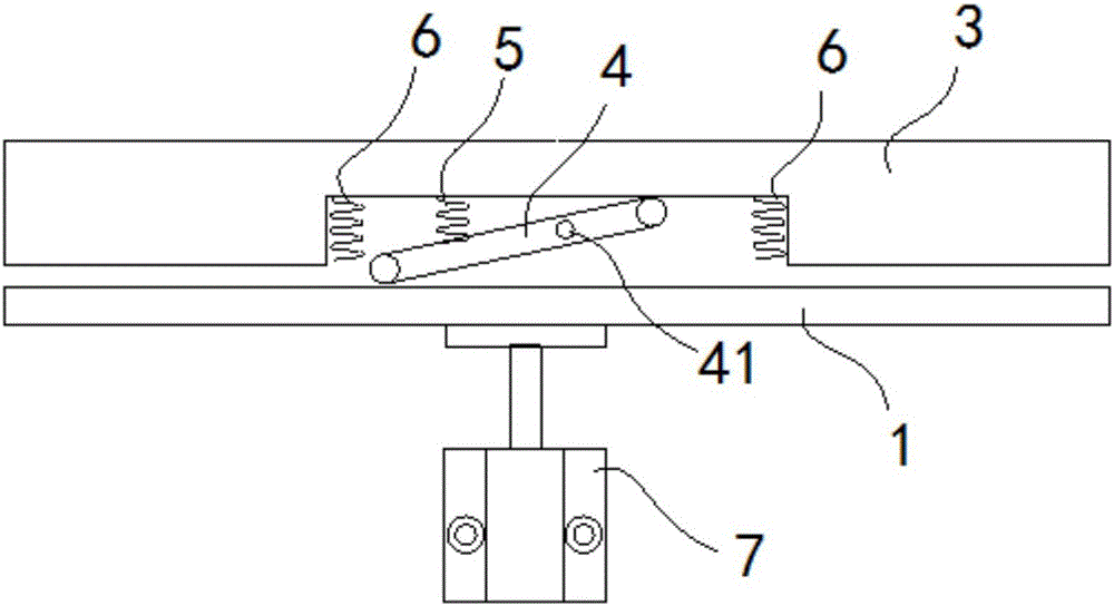
[0025] like figure 1 As shown, the clamping device of the chip mounter of the present invention includes: a first clamping plate 1 , a second clamping plate 3 , a lever 4 , a compression spring 5 , a tension spring 6 , and an air cylinder 7 .

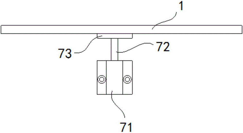
[0026] The first clamping plate 1 is arranged below the transmission belt 2 (not shown in the figure). The width of the first clamping plate 1 is greater than the width of the second clamping plate 3 . The first splint 1 is a straight plate, and a plurality of array holes can be set on the first splint 1 for inserting support nails. On the one hand, the quality of the first splint itself is reduced. When inserting the support pins, it can withstand the PCB board, avoid the depression in the middle of the PCB board, and reduce the patch error. like figure 2 As shown, a cylinder 7 is arranged below the first clamping plate 1 , and the cylinder 7 is connected to the lower surface of the first clamping plate 1 . The cylinder 7 includes...


PUM


Abstract

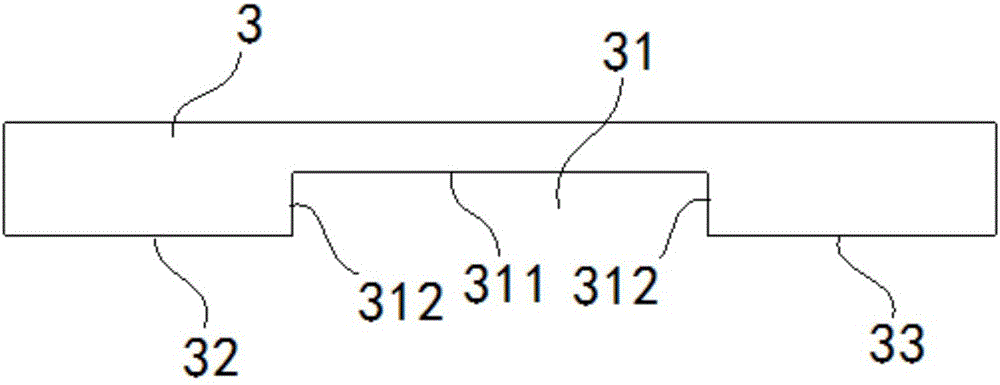
The invention discloses a surface mounting machine clamping device. The surface mounting machine clamping device includes a first clamping plate, a second clamping plate, a lever, a compression spring, tension springs and an air cylinder; the middle of the second clamping plate is provided with a groove which comprises a first groove surface and two second groove surfaces which are opposite to each other; the first end of the lever is arranged above the first clamping plate; the second end of the lever contacts with the first groove surface of the second clamping plate; the first end of the compression spring is connected with the lever; the second end of the compression spring is connected with the first groove surface; the first ends of the tension springs are connected with the first groove surface; and the air cylinder is connected with the lower surface of the first clamping plate. According to the surface mounting machine clamping device adopted, the lever, the compression spring and the tension springs are arranged between the first clamping plate and the second clamping plate, so that a buffering mechanism can be formed, and therefore, the first clamping plate and the second clamping plate slowly clamp a PCB, and damage to the PCB caused by large impact generated in a machining process can be avoided. The surface mounting machine clamping device has the advantages of simple structure, convenient operation, fast response, high machining precision, high production efficiency, low processing cost and high automation degree.

Description

Technical field: [0001] The invention belongs to the technical field of surface mounting, and in particular relates to a clamping device for a placement machine. Background technique: [0002] Surface Mount Technology (English full name Surface Mount Technology, SMT for short) is the most popular technology and process in the electronic assembly industry. The full name of PrintedCircuitBoard, referred to as PCB) surface or the surface of other substrates, and then through reflow or dip soldering and other methods to solder and assemble the circuit assembly technology. Mounter is a device used to achieve high-speed, high-precision placement of components. The clamping of the PCB board on the conveyor is divided into two processes: positioning and clamping. The positioning of the PCB board is completed by sensor monitoring. When the state of the trigger end switch of the PCB board changes, the transmission device considers the PCB board to be in place, and the clamping of th...

Claims


Application Information

Patent Timeline
IPC IPC(8): H05K3/30
CPCH05K3/303H05K2203/15
Inventor 董维平沈鹏董航
Owner SUZHOU SIKABO COMM TECH
Learn More