A high-stability force generator with compensation

A force generator, high stability technology, applied in the field of high stability force generator, can solve the problem of unstable force output capability of force generator, unstable force output capability of generator, large constant force or moment of force generator and other problems, to achieve the effect of improving radial uniformity, improving coaxiality, and reducing constant force

Active Publication Date: 2017-09-29
BEIJING PULIMEN ELECTRO MECHANICAL HIGH TECHN CO
View PDF3 Cites 0 Cited by
  • Summary
  • Abstract
  • Description
  • Claims
  • Application Information

AI Technical Summary

Problems solved by technology

Alnico magnets have a low temperature coefficient, but also low intrinsic coercive force, so the stability of magnetic properties is not high. Samarium cobalt magnets have high intrinsic coercive force, but the temperature coefficient is also high, and magnetic properties also appear during use. The phenomenon of unstable energy leads to the instability of the force output capability of the generator
Wrapping the outer circle of the magnetic steel with a thermal magnetic compensation sheet makes the assembly process poor. Because there is no positioning ring for positioning, the coaxiality between the magnetic steel and the shell is poor. In addition, there is no magnetic conducting ring at the end of the shell, and the magnetic field in the gap direction The internal divergence of the shell, both factors cause the annular magnetic field in the gap to be uneven, and any small displacement of the moving frame will cause the force output capability of the force generator to be unstable
[0003] Since both the aluminum alloy and the enameled wire have a certain residual magnetic permeability, the constant force or moment of the force generator will be large, which is also a factor that causes the force output capability of the force generator to be unstable.

Method used


Image

  • A high-stability force generator with compensation
  • A high-stability force generator with compensation
  • A high-stability force generator with compensation

Examples


Embodiment Construction

[0025] The high-stability force generator with compensation according to the present invention will be further described in detail with reference to the accompanying drawings and specific implementation.

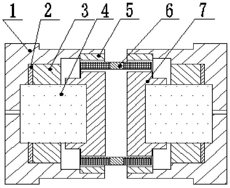
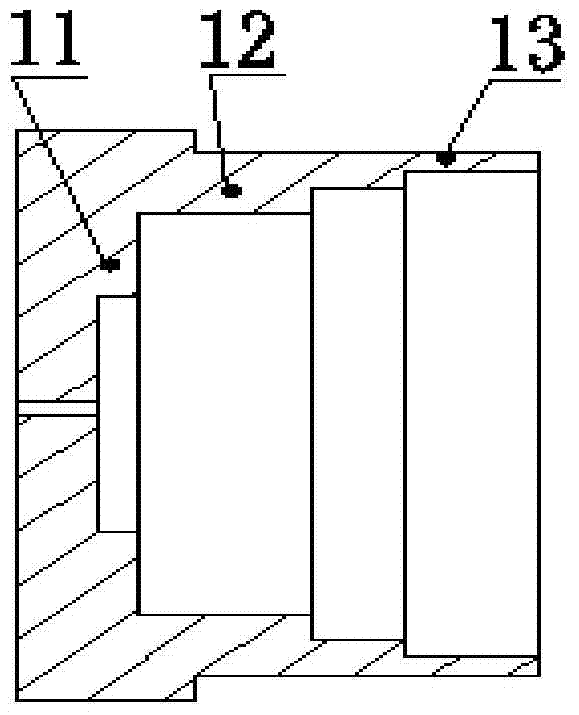
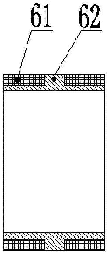
[0026] like Figure 1-Figure 3 As shown, the high stability force generator with compensation of the present invention includes a housing 1 , a compensation plate 2 , a positioning ring 3 , a magnetic steel 4 , a magnetic conducting ring 5 , a moving frame 6 , and a magnetizing ring 7 . in. The casing 1 has a hollow cavity structure of revolution, including a first cylinder 11, a second cylinder 12, and a third cylinder 13 that are sequentially connected and the inner cavities are connected to each other. The first cylinder 11, the second cylinder 12, The inner diameter of the third cylinder 13 gradually increases, and one end of each cylinder is provided with an outwardly protruding boss, so as to facilitate the axial positioning of each component in the inner cavity of th...


PUM


Abstract

The invention discloses a high-stability force generator with compensation, which comprises a shell, a compensation sheet, a positioning ring, a magnetic steel, a magnetic conducting ring, a moving frame, and a magnetizing ring. The shell, the magnetic conducting ring and the magnetic increasing ring are all made of magnetic conducting materials, and together with the magnetic steel, a closed-loop magnetic circuit is established, and the moving frame is a coil wound on the skeleton. When the coil is fed with direct current, the coil generates an electromagnetic force in the magnetic field that is consistent with the axial direction of the product. The force generators of the present invention should be used symmetrically in pairs in a mechanical unit. The invention adopts permanent magnet steel with low temperature coefficient and high magnetic performance to improve the force output capability, and the compensating sheet adopts soft magnetic sheet to compensate the influence of working temperature change on air gap magnetic density. The invention has the advantages of high force output capability, high force stability, convenient processing and manufacturing, etc., and can be used as a force feedback element in inertial instrumentation, servo control, and force or moment measurement.

Description

technical field [0001] The invention is suitable for the output of force or moment in precision mechanical equipment such as a high-precision accelerometer, a servo loop, and force or moment measurement, and in particular relates to a high-stability force generator with compensation. Background technique [0002] Permanent magnet force generators generally use permanent magnets with high magnetic properties, such as AlNiCo and SmCo. The outer circle of the magnet steel is wrapped with thermal magnetic compensation sheets. There is no positioning ring between the magnet steel and the shell. There is no magnetic ring, and the moving frame is generally made of ordinary enameled wire wound on an aluminum alloy skeleton. Alnico magnets have a low temperature coefficient, but also low intrinsic coercive force, so the stability of magnetic properties is not high. Samarium cobalt magnets have high intrinsic coercive force, but the temperature coefficient is also high, and magnetic p...

Claims


Application Information

Patent Timeline
Patent Type & Authority Patents(China)
IPC IPC(8): H02K51/00
Inventor 马建红袁朝阳孙玉彤董宏章李军周荣平
Owner BEIJING PULIMEN ELECTRO MECHANICAL HIGH TECHN CO
Why Eureka
Try Eureka