
Wire bonding structure and wire bonding method

A technology of wire bonding and wire bonding, which is applied in the direction of electrical components, electric solid devices, circuits, etc., can solve the problems of easy peeling of metal balls and solder pads, so as to ensure the original structure and function, increase the contact area, increase the The effect of resistance

Active Publication Date: 2015-11-25
SEMICON MFG INT (SHANGHAI) CORP
View PDF13 Cites 5 Cited by
  • Summary
  • Abstract
  • Description
  • Claims
  • Application Information

AI Technical Summary

Problems solved by technology

[0007] The purpose of this application is to provide a wire bonding structure and a wire bonding method to solve the problem of easy peeling of metal balls and pads in the prior art without affecting the existing chip structure and performance

Method used

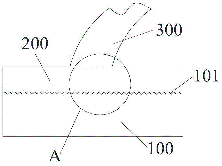
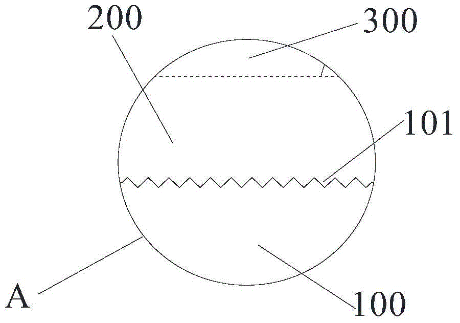
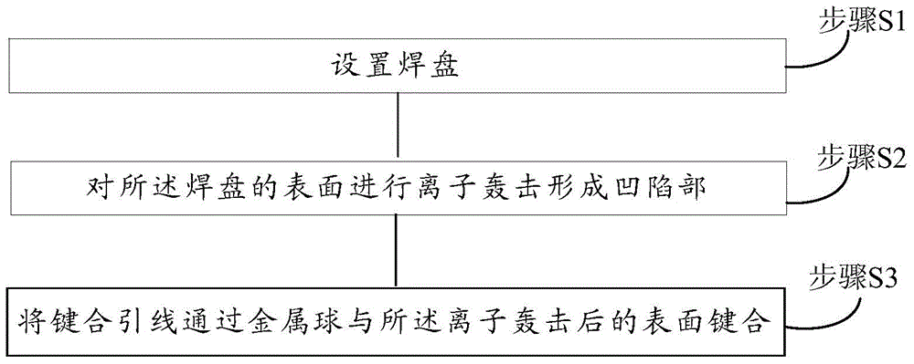

Image

  • Wire bonding structure and wire bonding method
  • Wire bonding structure and wire bonding method
  • Wire bonding structure and wire bonding method

Examples


Embodiment Construction

[0028] It should be pointed out that the following detailed descriptions are all illustrative and are intended to provide further explanations for the application. Unless otherwise indicated, all technical and scientific terms used herein have the same meaning as commonly understood by those of ordinary skill in the technical field to which this application belongs.

[0029] It should be noted that the terms used here are only for describing specific implementations, and are not intended to limit the exemplary implementations according to the present application. As used herein, unless the context clearly dictates otherwise, the singular form is also intended to include the plural form. In addition, it should also be understood that when “including” and / or “including” are used in this specification, it indicates There are features, steps, operations, devices, components, and / or combinations thereof.

[0030] For ease of description, spatially relative terms can be used here, such ...


PUM

PropertyMeasurementUnit
depthaaaaaaaaaa

Abstract

The invention provides a wire bonding structure and a wire bonding method. The wire bonding structure comprises a pad, a metal ball, and a bonding wire, wherein the metal ball is fixed on the pad; the bonding wire and the metal ball are arranged in an integrated mode; and the surface where the pad and the metal ball are contacted is provided with multiple depressions. As the surface where the pad and the metal ball are contacted is provided with multiple depressions, the contact area between the pad and the metal ball is increased; curved surface contact replaces the original plane contact, resistance when the pad and the metal ball are separated is increased, and the separation problem of the two can be effectively solved; and in addition, only the surface structure of the pad is improved, the fact that a huge amount of heat is formed due to processes such as high-temperature heating and electroplating does not happen, a newly-formed semiconductor device structure is not influenced at all, and the original structure and functions of a chip can be ensured.

Description

Technical field [0001] This application relates to the technical field of semiconductor manufacturing, and in particular to a wire bonding structure and a wire bonding method. Background technique [0002] With the continuous advancement of semiconductor device manufacturing processes, traditional wire bonding methods are gradually being replaced by new bonding processes, especially for chip bonding, in which ball contact bonding (BSOB) technology has been widely used The chip is being bonded. [0003] BSOB technology includes the beginning of the welding cycle, the welding tool (wedge) is moved to the first spot welding position, the first spot welding uses heat and ultrasonic energy to weld a metal ball on the surface of the chip pad, and then the wedge is raised to the arc The top position and move to form the required arc form. The second spot welding includes stitch bonding and tail wire. After bonding, the tail wire is used to form a tail wire, which is the formation of the ...

Claims


Application Information

Patent Timeline
Patent Type & Authority Applications(China)
IPC IPC(8): H01L23/488H01L21/60
CPCH01L2224/05H01L2224/85
Inventor 殷原梓高保林张菲菲
Owner SEMICON MFG INT (SHANGHAI) CORP
Learn More