
Infrared probe temperature measuring device

A technology of infrared probe and temperature measuring device, which is applied in the direction of measuring device, optical radiation measurement, radiation pyrometry, etc., can solve the problems of easy dusting of protective lenses, waste of human resources, heavy workload, etc., and prevent dust from falling into the to the surface of the lens, extend the maintenance period, and achieve the effect of a high level of automation

Inactive Publication Date: 2015-11-25
DONGGUAN NANNAR ELECTRONICS TECH
View PDF14 Cites 4 Cited by
  • Summary
  • Abstract
  • Description
  • Claims
  • Application Information

AI Technical Summary

Problems solved by technology

[0003] However, the existing temperature measuring devices are often installed below the axle box to detect the train axle temperature from bottom to top, and the protective lens of the probe is perpendicular to the detection path of the probe, which is also inclined upward; in this way, the upper end of the protective lens is prone to dust, which seriously affects the safety of the probe. Detection precision and accuracy; and manual regular inspection and cleaning are required, the level of intelligence is not high, the workload is heavy, and human resources are wasted

Method used


Image

  • Infrared probe temperature measuring device
  • Infrared probe temperature measuring device
  • Infrared probe temperature measuring device

Examples


Embodiment Construction

[0020] In order to make the technical solution of the present invention more clearly expressed, the present invention will be further described below in conjunction with the accompanying drawings.

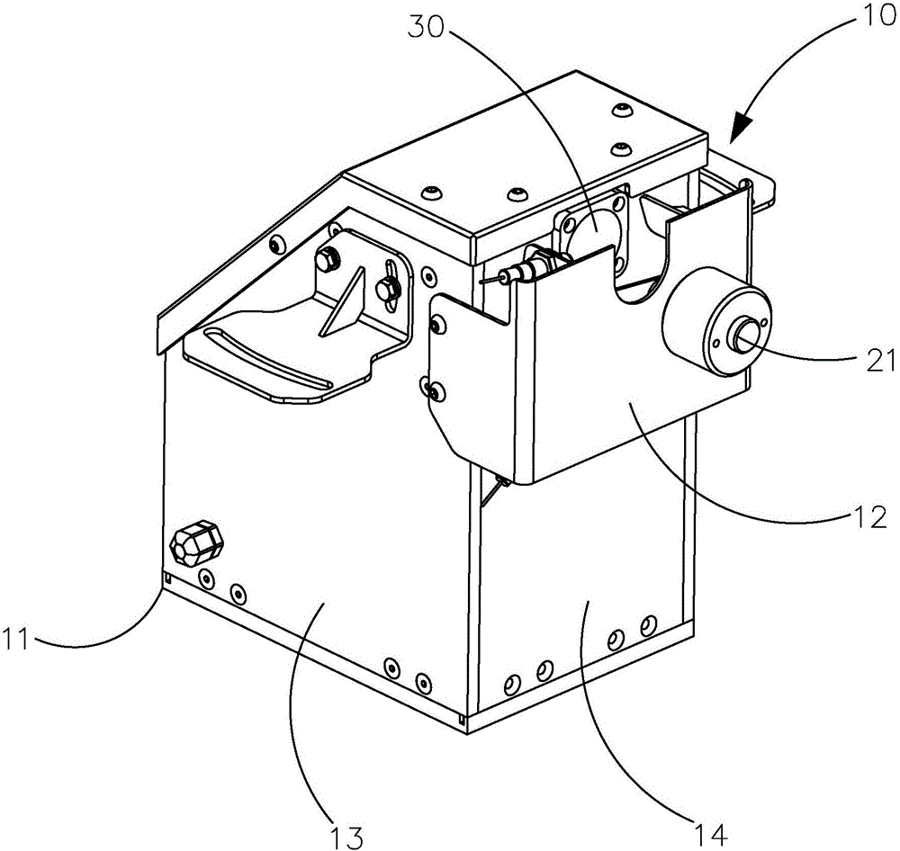
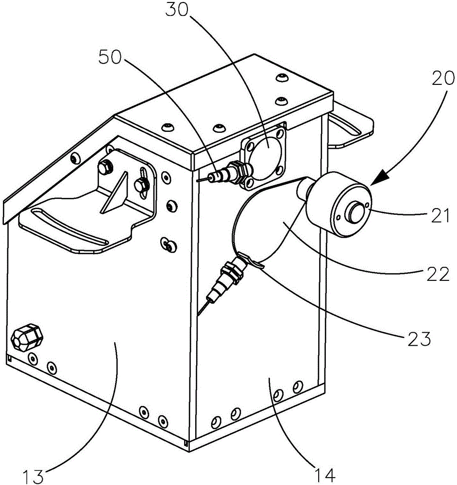
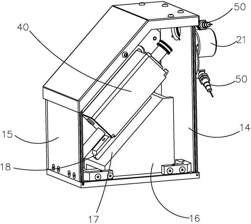
[0021] like Figure 1 to Figure 4 As shown, the present invention provides an infrared probe temperature measuring device, which is installed on both sides of the rail, and is used to detect the infrared radiation value of the axle box, convert the infrared radiation value into a corresponding current signal output, and obtain the axis of the running train. The temperature of the box changes, and the infrared probe temperature measuring device includes a box body 10, a lens 30 installed on the box body 10, an infrared probe 40 installed in the box body 10, and a cleaning device 20 installed outside the box body 10, The extension line of the infrared emitting direction of the infrared probe 40 passes through the protective mirror, and the cleaning device 20 regularly cleans the oute...


PUM


Abstract

Provided is an infrared probe temperature measuring device including a casing, a lens arranged on the casing, an infrared probe arranged in the casing, a cleaning device arranged in the casing, and two position sensors, the casing includes a body and a mount arranged outside the body, the position sensors are respectively and fixedly arranged at the upper part and the lower part of the mount, the cleaning device includes a rotary electromagnet, a rotating blade connected to the rotary electromagnet, and a hairbrush arranged on the rotating blade, the emitting directions of the position sensors face the rotary electromagnet, one end of the rotating blade is connected with the rotating shaft of the rotary electromagnet, the other end of the rotating blade is provided with a block, the rotary electromagnet drives the rotating blade to rotate around the rotating shaft to make the block of the rotating blade move ahead of the two position sensors successively, the hairbrush is arranged at the inner side of the rotating blade, and the hairbrush performs synchronous rotation along the rotating blade to clean the lens during the swing process of the rotating blade driven by the rotary electromagnet. The infrared probe temperature measuring device is high in automation and practicality, greatly prevents dust from falling to the surface of the lens, and greatly prolongs the maintenance period.

Description

technical field [0001] The invention relates to a shaft temperature detecting device, in particular to an infrared probe temperature measuring device. Background technique [0002] When the train is running, the axles and bearings rub against each other to generate heat. When there is a fault between the axle and the bearing, the friction force increases, the heat energy generated increases accordingly, and the temperature of the axle box also increases accordingly. Therefore, during the running of the train, by measuring the temperature change of the axle box, it can be determined whether the working state of the axle box is normal. In the prior art, in order to know the temperature change of the train axle box in time, it is often necessary to install a temperature measuring device on the track to detect the temperature of the axle box. [0003] However, the existing temperature measuring devices are often installed below the axle box to detect the train axle temperature...

Claims


Application Information

Patent Timeline
Patent Type & Authority Applications(China)
IPC IPC(8): G01J5/00G01J5/02
Inventor 辜勇彬曾德垚赵晓华陈黎明
Owner DONGGUAN NANNAR ELECTRONICS TECH
Learn More