Superheater metal wall temperature control method for thermal power unit

A technology of thermal power unit and control method, which is applied to the control of overheating temperature, steam overheating, lighting and heating equipment, etc., can solve problems such as the control effect depends on the operator, the inability to effectively control the metal wall temperature, and the over-temperature pipe burst accident, etc. To achieve the effect of simple on-site debugging process, improving safety and economy, and reducing labor intensity

Inactive Publication Date: 2015-11-25
LIAONING DONGKE ELECTRIC POWER
View PDF7 Cites 7 Cited by
  • Summary
  • Abstract
  • Description
  • Claims
  • Application Information

AI Technical Summary

Problems solved by technology

[0004] The above documents and patents are all researched from the perspective of improving the accuracy of wall temperature monitoring and building a real-time monitoring and evaluation system, providing a reliable reference for the operation of power plant operators, but these studies cannot replace the effective monitoring of metal wall temperature by operators. control
When the metal wall temperature of the superheater is overheated, only human intervention can be carried out. Due to the limitations of human intervention in time, space and energy, it will inevitably cause disturbances to the main parameters of the unit, and even cause overtemperature pipe burst accidents. The effect depends heavily on the technical level of the operator

Method used


Image

  • Superheater metal wall temperature control method for thermal power unit
  • Superheater metal wall temperature control method for thermal power unit

Examples


Embodiment Construction

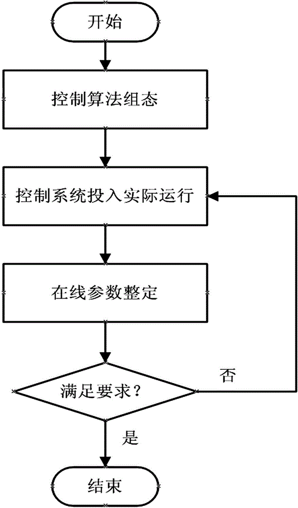
[0024] The present invention is a thermal power unit superheater metal wall temperature control method, such as figure 2 shown, including the following steps:

[0025] Step 1: Add superheater metal wall temperature control loop interfaces in the logic configuration fuel, feed water, and both sides screen overheating water and both sides high overheating water control loops in the original coordinated control system;

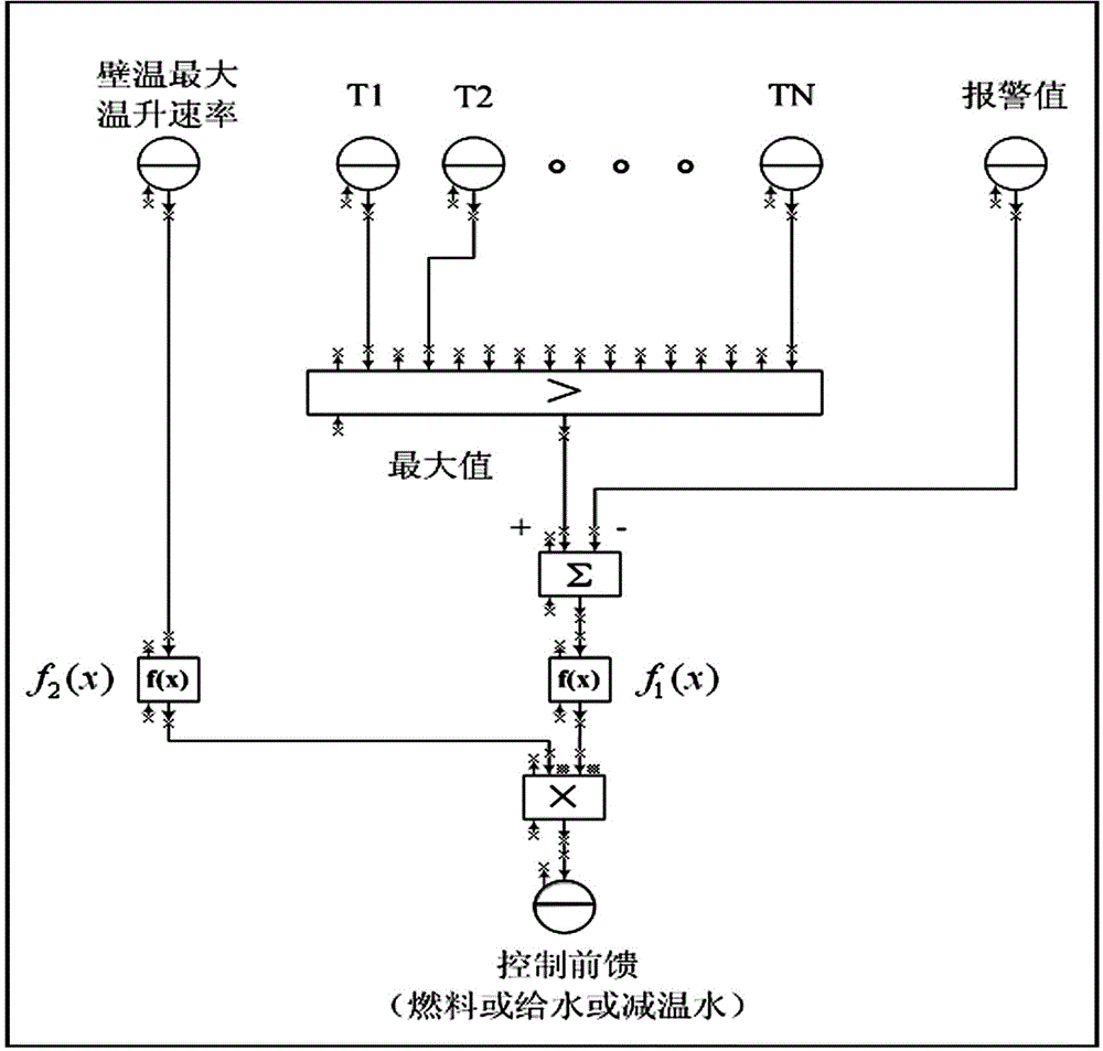
[0026] Step 2: Carry out the logic configuration of the metal wall temperature control loop of the superheater, and introduce its output into the interface of the metal wall temperature control loop of the superheater as fuel, feed water, over-desuperheating water on both sides, and over-desuperheating water on both sides feedforward signal;

[0027] Step 3: The control system is put into actual operation. According to the real-time operation curve, the parameters of the metal wall temperature control loop of the superheater are adjusted online to ensure that t...


PUM


Abstract

The invention belongs to the technical field of thermal control for power generating unit boiler safety and particularly relates to a superheater metal wall temperature control method for a thermal power unit, and specifically relates to a method for avoiding boiler superheater overheating and tube rupture in a power station. The method comprises the steps that superheater metal wall temperature control loop interfaces are added to control loops of logic configuration fuels of a coordinated control system, water supplying and platen superheater attemperation water on two sides and high-temperature superheater attemperation water on two sides; logic configuration of a superheater metal wall temperature control loop is conducted and output and introduced to the superheater metal wall temperature control loop interfaces, and the logic configuration is taken as a feedforward signal of control over the fuels, water supplying and platen superheater attemperation water on two sides and high-temperature superheater attemperation water on two sides; a control system is placed in actual operation, and superheater metal wall temperature control loop parameters are adjusted and set online according to a real-time operation curve; quick and stable responses of main parameters of the unit are guaranteed, and the superheater metal wall temperature is controlled in a reasonable range at the same time. Superheater overheating and tube rupture accidences are avoided effectively; the labor intensity is reduced; the operation safety and economy of the unit are improved.

Description

technical field [0001] The invention belongs to the technical field of thermal control technology for boiler safety of thermal power generating units, and in particular relates to a method for controlling the metal wall temperature of a superheater of a thermal power generating unit, in particular to a method for avoiding overtemperature explosion of a superheater of a power plant boiler. Background technique [0002] With the development of the electric power industry, the installed capacity of thermal power generating units is increasing day by day, becoming the main unit for frequency regulation and peak regulation in the power grid. In order to meet the needs of grid AGC and primary frequency regulation, large-capacity units have to frequently lift and lower loads in a large range, which puts forward higher requirements for the stable operation of unit parameters. At present, the typical unit coordination control system generally only controls the main unit parameters su...

Claims


Application Information

Patent Timeline
Patent Type & Authority Applications(China)
IPC IPC(8): F22G5/20
Inventor 王礼张亮王洪凯辛岩褚云山
Owner LIAONING DONGKE ELECTRIC POWER
Why Eureka
Try Eureka