Injection technology and injection equipment of chemical autogenous heat system in heavy oil reservoir
A heavy oil reservoir, self-heating technology, applied in chemical instruments and methods, production fluids, wellbore/well components, etc., can solve the problems of complex operation, difficult implementation of injection process and high risk factor
- Summary
- Abstract
- Description
- Claims
- Application Information
AI Technical Summary
Problems solved by technology
Method used
Image
Examples
Embodiment 1
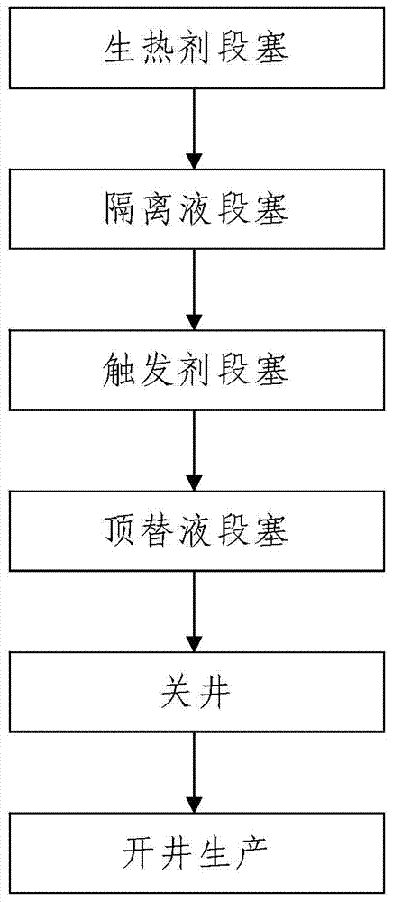
[0081] Such as figure 1 , figure 2 and image 3 The injection process of a chemical self-generating heat system in a heavy oil reservoir is shown, and the chemical self-generating heat system is injected into the heavy oil reservoir where the target well 8 is located by adopting a cold recovery method or a steam injection thermal recovery method; the chemical self-generating heat system It includes a heat generating agent and a triggering agent and it is an alkaline self-heating system or an acidic self-heating system, and the heat generating agent includes active wave metal particles with a particle size not greater than 400 mesh and a coating layer for wrapping active wave metal particles; The living wave metal particles of the alkaline self-generating heat system are aluminum powders, the coating layer used to wrap the aluminum powder is a paraffin coating layer or an aluminum stearate coating layer, and the trigger agent of the alkaline self-generating system is NaOH po...
Embodiment 2
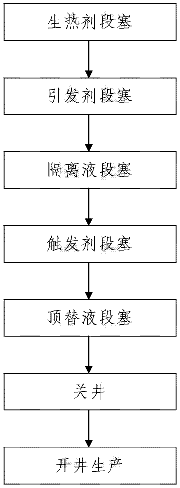
[0173] In this example, if figure 2 As shown, the difference from Example 1 is that the temperature T of the heavy oil reservoir where the target well 8 is located is less than or equal to 60°, and the chemical self-heating system is injected into the heavy oil reservoir where the target well 8 is located by adopting a cold recovery method, The process is as follows:
[0174] Step 301, heat generating agent slug: according to the method described in step 101, complete the heat generating agent slug process;
[0175] Step 302, initiator slug: inject the pre-prepared initiator solution into the heavy oil reservoir where the target well 8 is located; the initiator solution is a solution formed by uniformly mixing the initiator and water, and the initiator solution The mass concentration of the initiator in the medium is 35kg / m 3 ~45kg / m 3 ;
[0176] The injection volume of described initiator solution is 0.5m 3 ~1.8m 3 ;
[0177] Step 303, according to the method describe...
Embodiment 3
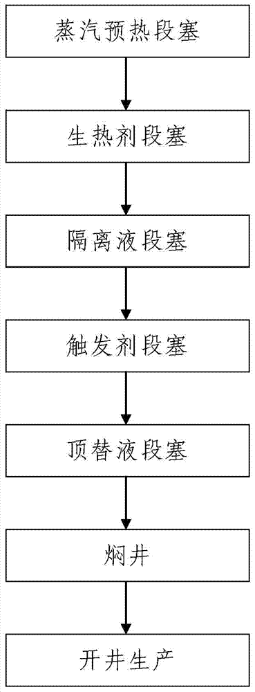
[0189] In this example, if image 3 As shown, the difference from Example 1 is that: the temperature T of the heavy oil reservoir where the target well 8 is located is > 120°, according to the method described in step 201 to step 204, the steam injection thermal recovery method is used to inject steam into the target well. The chemical self-heating system is injected into the heavy oil reservoir where 8 is located, and the process is as follows:
[0190] Step 201, steam preheating slug: Inject 280 to 320 tons of steam into the heavy oil reservoir where the target well 8 is located to preheat the heavy oil reservoir where the target well 8 is located;
[0191] Step 202, according to the method described in step 101 to step 104, complete the heat generating agent slug, spacer fluid slug, trigger agent slug and displacement fluid slug process from first to last;
[0192] Step 203, soaking the well: soaking the target well 8 for 3d to 7d;
[0193] Step 204, open the well for pro...
PUM
| Property | Measurement | Unit |
|---|---|---|
| particle size | aaaaa | aaaaa |
| viscosity | aaaaa | aaaaa |
Abstract
Description
Claims
Application Information
 - R&D
- Intellectual Property
- Life Sciences
- Materials
- Tech Scout
- Unparalleled Data Quality
- Higher Quality Content
- 60% Fewer Hallucinations
Browse by: Latest US Patents, China's latest patents, Technical Efficacy Thesaurus, Application Domain, Technology Topic, Popular Technical Reports.
© 2025 PatSnap. All rights reserved.Legal|Privacy policy|Modern Slavery Act Transparency Statement|Sitemap|About US| Contact US: help@patsnap.com


