
Speed detection device and installation method thereof

A speed measurement device and installation method technology, applied in the direction of measuring device, linear/angular velocity measurement, speed/acceleration/impact measurement, etc., can solve the problems of increased wear, small speed measurement induction gap, and lower overall reliability level, etc., to achieve strengthening Anti-interference ability, wide range of sensing gap, and good assembly adaptability

Active Publication Date: 2015-11-25
湖南广思科技有限公司
View PDF8 Cites 5 Cited by
  • Summary
  • Abstract
  • Description
  • Claims
  • Application Information

AI Technical Summary

Problems solved by technology

[0003] Among them, the photoelectric speed sensor contains a transmission bearing inside. Under the compound conditions of locomotive vibration, impact, high speed and long-term operation, the wear of the transmission bearing limits the overall reliability of the sensor; on the other hand, the sensor passes through the shaft. The square tenon at the end of the locomotive and the square hole sleeve at the end of the locomotive axle are connected to achieve transmission and speed measurement. Factors such as the matching size, lubrication state, and relative axial movement of the two connecting parts determine the wear between the two. If there is a slight abnormality, the wear will increase sharply. , rapidly lowering the overall reliability level or failing
[0004] The Hall speed sensor outputs the speed signal on the outer ring of the radial non-contact induction speed measuring toothed disc. The installation method of the shaft end is completely different from that of the photoelectric speed sensor. The sensing distance between the tooth top of the speed measuring tooth disc and the end face of the sensing head is 0.5mm -2.0mm, the sensor gap of the speed measurement is small, and the assembly adaptability is poor

Method used


Image

  • Speed detection device and installation method thereof
  • Speed detection device and installation method thereof
  • Speed detection device and installation method thereof

Examples


Embodiment Construction

[0031] In order to facilitate the understanding of the present invention, the present invention will be described more fully below with reference to the associated drawings. Preferred embodiments of the invention are shown in the accompanying drawings. However, the present invention can be embodied in many different forms and is not limited to the embodiments described herein. On the contrary, these embodiments are provided to make the understanding of the disclosure of the present invention more thorough and comprehensive.

[0032] It should be noted that when an element is referred to as being “fixed” to another element, it can be directly on the other element or there can also be an intervening element. When an element is referred to as being "connected to" another element, it can be directly connected to the other element or intervening elements may also be present.

[0033] Unless otherwise defined, all technical and scientific terms used herein have the same meaning as...

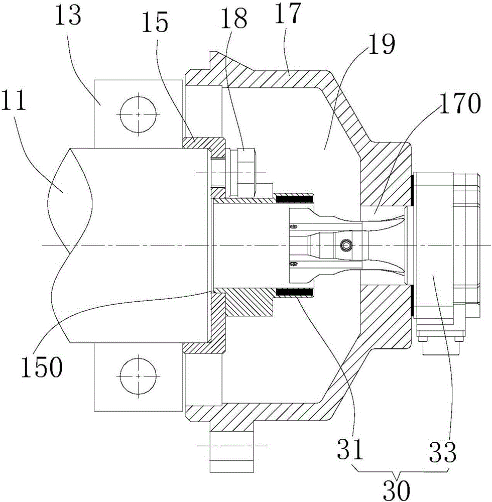

PUM


Abstract

The invention discloses a speed detection device which comprises a disk and a sensor matched with the disc. The disc comprises a disc body and multiple magnetic parts arranged in the disc body, the disc body is internally provided with a magnetic induction passage, and the sensor comprises an inductive probe; the multiple magnetic parts are sequentially arranged on the disc body and form a magnetic field which changes periodically in the magnetic induction passage, and the inductive probe extends into the magnetic induction passage to cut magnetic induction lines of the magnetic field and outputs a periodical pulse signal. According to the speed detection device, the range of an inductive gap of the sensor is large, the eccentric magnitude is allowed to be large during installation, and assembly adaptability is good; rotating parts and driving parts do not exist in the interior of the speed detection device, saved spaces are all assigned to an electrical part to enhance capacity of resisting disturbance, and safety and reliability are achieved. The invention further provides an installation method of the speed detection device.

Description

technical field [0001] The invention belongs to the field of locomotive speed measurement, in particular to a speed measurement device and an installation method thereof. Background technique [0002] At present, in the field of railway locomotive speed measurement, photoelectric speed sensors with 200 pulses per circle or non-contact Hall speed sensors with 80 pulses per circle are mainly used. [0003] Among them, the photoelectric speed sensor contains a transmission bearing inside. Under the compound conditions of locomotive vibration, impact, high speed and long-term operation, the wear of the transmission bearing limits the overall reliability of the sensor; on the other hand, the sensor passes through the shaft. The square tenon at the end of the locomotive and the square hole sleeve at the end of the locomotive axle are connected to achieve transmission and speed measurement. Factors such as the matching size, lubrication state, and relative axial movement of the two...

Claims


Application Information

Patent Timeline
Patent Type & Authority Applications(China)
IPC IPC(8): B61C17/00G01P3/481
Inventor 彭俊吉樊翠萍王晓冰范增昌刘向平李笑龙陈文汉
Owner 湖南广思科技有限公司
Learn More