Mold manufacturing method based on three-dimensional printing

A technology of three-dimensional printing and mold manufacturing, which is applied in the field of mold manufacturing, can solve the problems of long processing cycle, complicated process, poor cooling effect of mold waterway, etc., and achieve the effect of reducing processing risk and shortening processing cycle

Inactive Publication Date: 2015-11-25
BEIJING UREAL 3D TECH CO LTD
View PDF2 Cites 5 Cited by
  • Summary
  • Abstract
  • Description
  • Claims
  • Application Information

AI Technical Summary

Problems solved by technology

[0004] In order to solve the above problems, the present invention provides a mold manufacturing method based on three-dimensional printing, which can not only solve the design problem of poor cooling effect of traditional mold water channels, but also solve the problem of long processing period and complex process of traditional molds

Method used


Image

  • Mold manufacturing method based on three-dimensional printing
  • Mold manufacturing method based on three-dimensional printing
  • Mold manufacturing method based on three-dimensional printing

Examples


Embodiment 1

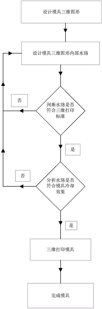
[0033] 1. According to the overall shape of the mold, select the number, shape and size of the mold waterways.

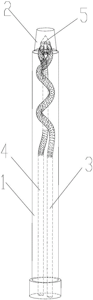
[0034] Such as figure 2 As shown, the shape of the mold is basically a cylinder, the lower end is a uniform cylinder 1 with a middle diameter of 20 mm; the upper end is a circular frustum 2 with a diameter of the upper end circle of 13 mm.

[0035] The mold has only one water inlet and one water outlet, and one waterway fully meets the cooling requirements and flow rate, so the number of waterways is selected as one.

[0036] According to the shape of the mould, the cross-sectional shape of the lower water inlet channel 3 and the outlet water channel 4 is selected as a circle with a diameter of 4 mm. Wherein the water inlet waterway 3 is a spiral rising type, and its purpose is to play cooling effect to the greatest extent, and the water outlet waterway 4 descends along the center, avoids the water inlet waterway 3, and leads to the water outlet waterway 4 through...

Embodiment 2

[0049] 1. According to the overall shape of the mold, select the number, shape and size of the mold waterways.

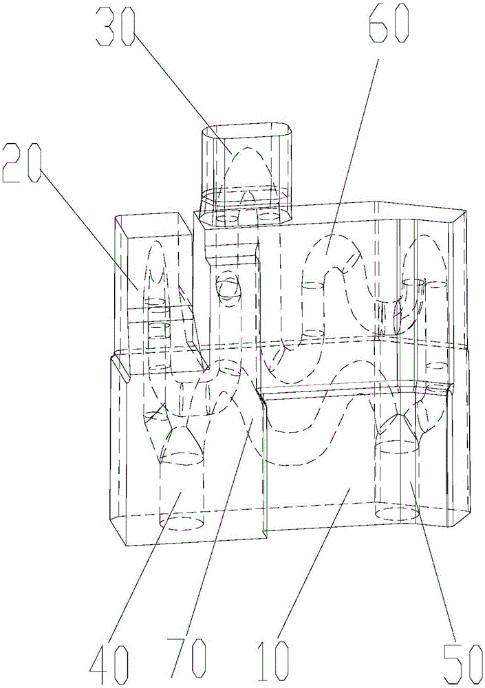
[0050] Such as image 3 As shown, the mold body 10 is a special-shaped structure, and the whole is a deformed cuboid with a length of about 50 mm and a width of about 14 mm; one side has an independent special-shaped boss 20 with a length of about 11 mm and a width of about 9 mm; the top has a waist Shaped boss 30, its length is about 12mm, and width is about 6.5mm; Water inlet 40 and water outlet 50 diameters are 6mm.

[0051] The mold has only one water inlet and one water outlet, and the number of waterways is temporarily selected as one.

[0052] According to the shape of the mould, due to the small size of the special-shaped boss 20 and the waist-shaped boss 30, the cross-sectional shape of the first waterway 60 is conventionally selected as a circle with a diameter of 3mm; since the flow rate of the first waterway 60 is obviously smaller than that of the wate...


PUM


Abstract

The invention provides a mold manufacturing method based on three-dimensional printing. The mold manufacturing method based on three-dimensional printing is characterized by comprising the following steps of designing a three-dimensional mold figure; designing a water channel inside the three-dimensional mold figure; judging whether the water channel meets the standard of three-dimensional printing, if not, returning to the step of designing the water channel inside the three-dimensional mold figure to design the water channel again, and if yes, continuing the follow-up steps; analyzing whether the water channel meets the request for the cooling effect of a mold, if not, returning to the step of designing the water channel inside the three-dimensional mold figure, and if yes, continuing the follow-up steps; and printing the mold figure through a three-dimensional printer to form a mold. The mold manufacturing method based on three-dimensional printing can solve the design problem that a water channel of a traditional mold has poor the cooling effect, and can also solve the problem that traditional mold machining is long in period and complex in technological process.

Description

technical field [0001] The invention relates to a mold manufacturing method, in particular to a mold manufacturing method based on three-dimensional printing technology. Background technique [0002] Mold refers to a production tool that can produce parts with certain shape and size requirements. In production and life, about 80% of the objects are processed by molds. We are in contact with products produced by molds all the time. It can be said that molds are the mother of industry. [0003] However, most injection molding molds have a cooling water system, that is, a waterway. The quality of mold waterway design directly affects product quality and production cost. Due to the influence of the processing method, the design of the existing mold waterway can only design a simple waterway, which seriously restricts the cooling effect of the waterway. As for the overall processing method of the mold, the existing mold has to go through a long process from blanking to rough a...

Claims


Application Information

Patent Timeline
IPC IPC(8): B29C45/73B29C33/38
CPCB29C45/7312B29C33/3835B29C33/3842
Inventor 王博文张国良
Owner BEIJING UREAL 3D TECH CO LTD
Why Eureka
Try Eureka