
Cage terminal wire remover

A terminal and cage-type technology, which is applied in the field of cage-type terminal wire withdrawal, can solve problems such as low efficiency and troublesome cage-type terminal wire removal, so as to improve wire removal efficiency, reduce disassembly and wire removal time, and avoid secondary wire removal Effect

Active Publication Date: 2017-01-11
CHANGCHUN RAILWAY VEHICLE FACILITIES
View PDF5 Cites 0 Cited by
  • Summary
  • Abstract
  • Description
  • Claims
  • Application Information

AI Technical Summary

Problems solved by technology

[0003] In order to solve the technical problem of cumbersome and low-efficiency dismantling of cage-type terminals for reading lights, the invention provides a cage-type terminal wire remover

Method used


Image

  • Cage terminal wire remover
  • Cage terminal wire remover
  • Cage terminal wire remover

Examples


Embodiment Construction

[0013] The present invention will be described in further detail below in conjunction with the accompanying drawings.

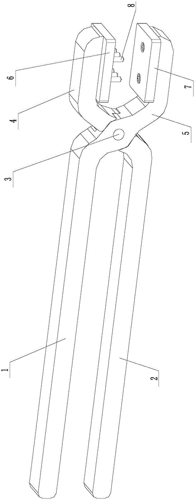
[0014] Such as Figure 2 to Figure 5 As shown, the cage terminal wire remover of the present invention includes a fixed handle 1, a movable handle 2, a rotating shaft 3, a movable jaw 4, a fixed jaw 5, an upper pad 6, a lower pad 7 and eight needle points that are conical The thimble 8; the movable handle 2 is rotationally connected with the fixed handle 1 through the rotating shaft 3, the movable jaw 4 is fixed on the front end of the movable handle 2, the fixed jaw 5 is fixed on the front end of the fixed handle 1, and the upper block 6 is fixed on the movable handle by screws. On the inner side of the jaw 4, the lower block 7 is fixed on the inner side of the fixed jaw 5 by screws; eight thimbles 8 are divided into two rows along the longitudinal direction of the rotating shaft 3 and fixed on the upper block 6, and the two rows of thimbles 8 are fixed alon...


PUM


Abstract

The invention provides a cage type terminal wire disassembling clamp and relates to the technical field of cage type terminal wire disassembling in maintenance for passenger train lamps and the like. The cage type terminal wire disassembling clamp comprises a fixed handle, a movable handle, a rotation shaft, a movable jaw, a fixed jaw, an upper cushion block, a lower cushion block and a plurality of ejection pins. The movable handle is rotatably connected with the fixed handle through the rotation shaft. The movable jaw is fixed to the front end of the movable handle. The fixed jaw is fixed to the front end of the fixed handle. The upper cushion block is fixed to the inner side face of the movable jaw through a screw. The lower cushion block is fixed to the inner side face of the fixed jaw through a screw. The ejection pins are divided into two rows to be fixed to the upper cushion block in the longitudinal direction of the rotation shaft. The distance between the two rows of ejection pins in the horizontal direction of the rotation shaft is equal to that between two pin insertion holes of a cage type terminal. The cage type terminal wire disassembling clamp can be used for disassembling eight wire ends at a time in groups, wire disassembling efficiency is improved by more than 5 times, wire disassembling time is shortened, and secondary wire disassembling caused by wire cutting is avoided.

Description

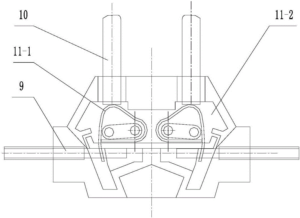
technical field [0001] The invention relates to the technical field of cage-type terminal wire unwinding in the maintenance of railway passenger car lamps and the like, in particular to a cage-type terminal wire remover. Background technique [0002] At the present stage, almost all lamps and lanterns of passenger cars use cage-type terminals for wiring, which is reliable and convenient. figure 1 As shown, one way is to use the pin 10 to pass through the pin hole of the insulator 11-2 of the cage terminal 11 to apply a certain pressure to the spring clamping piece 11-1, so that the spring clamping piece 11-1 is released, so that the wire 9 is loose, and then pulls down lead 9, must be pressed one by one during operation, just can finish unwiring operation, cumbersome. Another way is to use bolt cutters to cut off the part of the wire near the cage terminal, and then concentrate on the wire ends pressed on the cage terminal and then remove it with a pin, which is troublesome...

Claims


Application Information

Patent Timeline
Patent Type & Authority Patents(China)
IPC IPC(8): B25B7/22B25B27/00
CPCB25B7/22B25B27/00
Inventor 魏建民张永利
Owner CHANGCHUN RAILWAY VEHICLE FACILITIES
Learn More