
An auxiliary stitch removal device and stitch removal method for knitted sheets

The technology of a knitted sheet and a transmission device is applied in the field of fiber yarn knitting processing, and can solve the problems of time-consuming and laborious, single function, affecting the efficiency of stitching work, etc.

Active Publication Date: 2021-10-15
安徽三泰服饰科技有限公司
View PDF9 Cites 0 Cited by
  • Summary
  • Abstract
  • Description
  • Claims
  • Application Information

AI Technical Summary

Problems solved by technology

[0002] In the fiber knitting industry, there will inevitably be defective products or unqualified knitted products. In order to reduce the waste of these products, these products are generally recycled. At this time, these defective knitted products need to be recycled. In order to recycle the removed fiber threads, in knitting production, in order to improve the efficiency of stitch removal, it is often necessary to use auxiliary stitch removal devices, but the existing stitch removal devices are often simple in structure and single in function, generally only By controlling the rotation of the motor to assist in winding and taking up the thread, it is still necessary to manually hold the end of the defective knitted piece and cooperate with the guide to take up the thread to avoid excessive concentration of the thread taking up, and to control the motor according to the progress of the thread taking up while cooperating with the thread taking up Start and stop, so that too much manual operation is still required in the process of stitch removal, which is labor intensive, time-consuming and laborious, and affects the efficiency of stitch removal

Method used

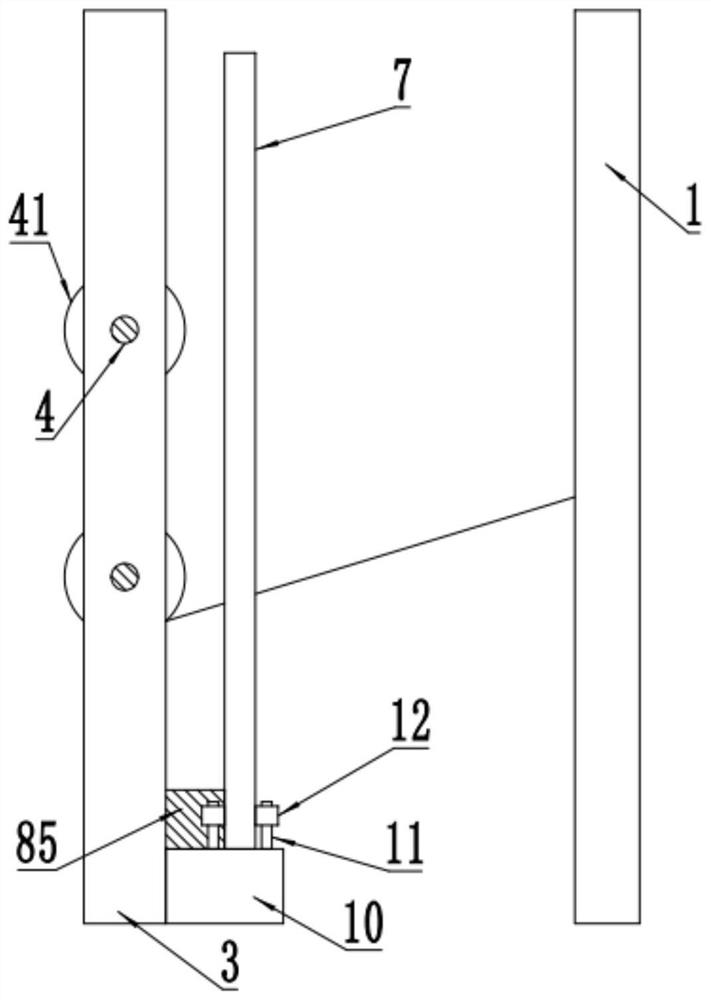
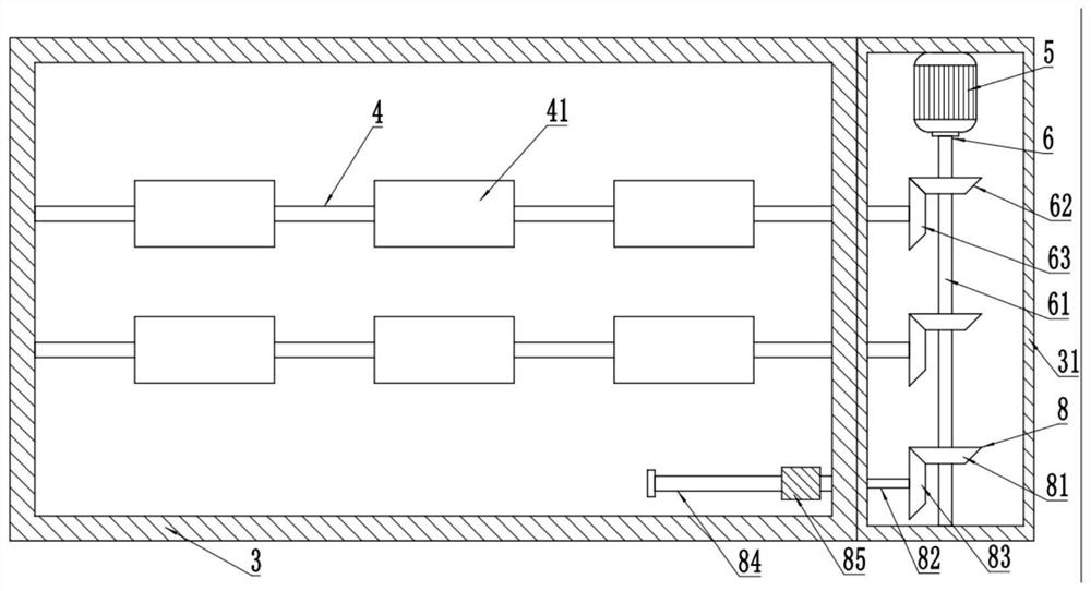
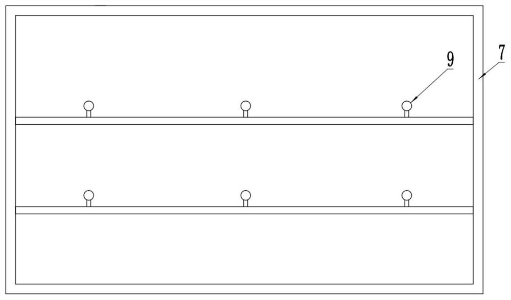

Image

  • An auxiliary stitch removal device and stitch removal method for knitted sheets
  • An auxiliary stitch removal device and stitch removal method for knitted sheets
  • An auxiliary stitch removal device and stitch removal method for knitted sheets

Examples


Embodiment Construction

[0035] In order to make the purpose, technical solutions and advantages of the present disclosure clearer, the present disclosure will be further described in detail below in conjunction with specific embodiments.

[0036] It should be noted that, unless otherwise defined, the technical terms or scientific terms used in one or more embodiments of the present specification shall have ordinary meanings understood by those skilled in the art to which the present disclosure belongs. "First", "second" and similar words used in one or more embodiments of the present specification do not indicate any order, quantity or importance, but are only used to distinguish different components. "Comprising" or "comprising" and similar words mean that the elements or items appearing before the word include the elements or items listed after the word and their equivalents, without excluding other elements or items. Words such as "connected" or "connected" are not limited to physical or mechanica...


PUM


Abstract

One or more embodiments of this specification provide an auxiliary stitch removal device and stitch removal method for knitted sheets, including a clamping frame, on which a clamping mechanism is provided to clamp the end of the knitted sheet, and the clamping frame There is a wire take-up frame on one side, and a driving chamber is fixed at the side end of the wire take-up frame. The end is mechanically connected to the motor, and the output end is mechanically connected to the take-up shaft to drive the take-up drum to rotate and take up the wire. The wire frame is set on the side of the wire take-up frame close to the clamping frame, and is mechanically connected through the input end of the wire transmission device. In the take-up transmission device, the output end is mechanically connected to the bottom of the wire frame, so that the knitted piece passes through the collar on the wire frame, and is driven by the wire transmission device to move laterally to and fro, so as to achieve automatic uniformity towards the wire take-up barrel Reel up.

Description

technical field [0001] One or more embodiments of this specification relate to the technical field of fiber yarn knitting processing, and in particular to an auxiliary stitch removal device and a stitch removal method for knitted sheets. Background technique [0002] In the fiber knitting industry, there will inevitably be defective products or unqualified knitted products. In order to reduce the waste of these products, these products are generally recycled. At this time, these defective knitted products need to be recycled. In order to recycle the removed fiber threads, in knitting production, in order to improve the efficiency of stitch removal, it is often necessary to use auxiliary stitch removal devices, but the existing stitch removal devices are often simple in structure and single in function, generally only By controlling the rotation of the motor to assist in winding and taking up the thread, it is still necessary to manually hold the end of the defective knitted ...

Claims


Application Information

Patent Timeline
Patent Type & Authority Patents(China)
IPC IPC(8): D01G11/00
CPCD01G11/00Y02W30/66
Inventor 梁丙青姚海涛常娟娟
Owner 安徽三泰服饰科技有限公司
Learn More