Clamping and fixing method for part blank

A fixing method and a technology of parts, which are applied in the direction of clamping, metal processing machinery parts, positioning devices, etc., can solve problems such as surface chattering of parts, adverse effects of tools, etc., and achieve the goals of reducing overhang length, improving surface quality, and reducing production time Effect

Inactive Publication Date: 2015-11-25
HARBIN
View PDF5 Cites 0 Cited by
  • Summary
  • Abstract
  • Description
  • Claims
  • Application Information

AI Technical Summary

Problems solved by technology

[0003] The technical problem to be solved by the present invention: when the traditional part blank is clamped and fixed by the pressure plate, the adverse effect on the tool and the problem of chatter lines on the surface of the part

Method used


Image

  • Clamping and fixing method for part blank
  • Clamping and fixing method for part blank
  • Clamping and fixing method for part blank

Examples


Embodiment Construction

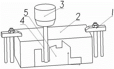
[0013] The installation and working methods of the present invention will be described below in conjunction with the accompanying drawings.

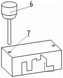
[0014] (1) Drill 1-2 bolt holes at the original pressure plate of the blank, such as figure 2 shown

[0015] Use the φ12 drill bit 6 to drill the bolt hole 7, the hole position is 15mm away from the edge of the blank, and 10-30mm away from the part.

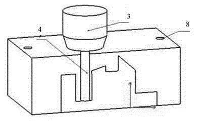
[0016] (2) Screw the bolts into the part blank, such as image 3 shown

[0017] Screw the inner hexagonal bolt 10 into the corresponding bolt hole of the part blank, the upper surface of the bolt should be lower than the upper surface of the part blank, so that the tool feeding of the part will not be affected during processing, and the overhang length 9 of the tool will also be reduced by 20-30mm.


PUM


Abstract

The invention relates to a clamping and fixing method for a part blank. Firstly, a plurality of clamping points are selected on a work surface of the blank every 300-500 mm according to the shape of a part, and it is guaranteed that the positions of the clamping points are 30 mm away from the biggest outline of the horizontal plane of the part; secondly, the part blank is arranged on a worktable, threaded through holes are machined in the part blank with the clamping points as the benchmark, and the threaded through holes penetrate through the worktable; and thirdly, the part blank and the worktable are fastened together through bolts, so that the part blank is clamped and fixed. By means of the special clamping and fixing method, the extended length of a tool is reduced when the part blank is machined, the surface quality of the machined part is improved, the workload is lightened, and the production time for the part is shortened.

Description

technical field [0001] The invention belongs to the field of mechanical clamping and relates to a clamping and fixing method for part blanks. Background technique [0002] The parts are generally processed on the CNC machine tool by the traditional pressure plate pressing method, such as figure 1 As shown, this method is to press the pressing plate 1 on the part blank 2. Since the pressing plate 1 has a certain height, this seriously affects the processing method of the part during processing, and it is very easy to cause the tool 4 to collide with the pressing plate 1, resulting in damage to the tool 4. Moreover, in order to prevent the tool 4 from colliding with the pressure plate 1, the way of cutting the tool will be forcibly changed when programming the CNC machining program, which will cause redundant tool paths and greatly reduce the processing efficiency. When processing deep cavity parts 5, in order to avoid the collision between the cutter head and the pressure pl...

Claims


Application Information

Patent Timeline
Patent Type & Authority Applications(China)
IPC IPC(8): B23Q3/06
CPCB23Q3/069
Inventor 任婉宁孙润麒
Owner HARBIN
Why Eureka
Try Eureka