Valve control device and valve control method

A valve control and control deviation technology, applied in the direction of flow control, electrical control, computer control, etc., can solve the problems of the deterioration of the valve opening to the target, the controllability of the cooling water flow adjustment, etc., to improve the settability. Effect

Inactive Publication Date: 2015-11-18
MIKUNI CORP
View PDF6 Cites 0 Cited by
  • Summary
  • Abstract
  • Description
  • Claims
  • Application Information

AI Technical Summary

Problems solved by technology

[0006] However, the above-mentioned throttle valve adjusts the amount of air sucked into the engine, whereas the coolant valve adjusts the flow rate of cooling water for cooling the engine. Therefore, there is a problem that the direction of the valve is different from that of the throttle valve. The settling of the target opening deteriorates, that is, the controllability of the cooling water flow regulation deteriorates

Method used


Image

  • Valve control device and valve control method
  • Valve control device and valve control method
  • Valve control device and valve control method

Examples


Embodiment Construction

[0020] Hereinafter, embodiments of the present invention will be described with reference to the drawings.

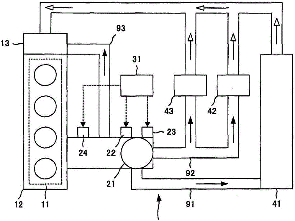
[0021] First, the engine cooling system of this embodiment will be described. figure 1 It is a schematic diagram showing the engine cooling system of this embodiment.

[0022] Such as figure 1 As shown, the engine cooling system 1 of this embodiment includes an engine 11, a water cooling jacket 12, a water pump 13, a cooling water valve 21, a motor 22, a position sensor 23, a water temperature sensor 24, an ECU (Engine Control Unit) 31, a radiator 41, a heater 42. Restrictor 43, main flow conduit 91, sub flow conduit 92, bypass flow conduit 93.

[0023] The engine cooling system 1 circulates cooling water through the main flow conduit 91 , the sub-flow conduit 92 , or the bypass flow conduit 93 , and controls the temperature of the engine 11 through the water cooling jacket 12 .

[0024] The engine 11 is an internal combustion engine of a vehicle such as an automobil...


PUM


Abstract

This valve control device, which controls a drive device that drives a valve, is provided with: an operation quantity calculation unit that calculates the operation quantity of the drive device at a predetermined sampling period on the basis of the control deviation between the target value for the valve aperture and the actually measured value for the valve aperture; a state determination unit that determines that the valve is in either a stationary state or a transient state; and a first correction unit that, when it has been determined by the state determination unit that the valve is in the stationary state, outputs a predetermined first correction value that is in accordance with the sign of the control deviation, and corrects the operation quantity calculated by the operation quantity calculation unit by the first correction value.

Description

technical field [0001] The invention relates to a valve control device and a valve control method for controlling an electronic control valve. Background technique [0002] Conventionally, a technique of electronically controlling a valve by feedback control such as PID (Proportional Integral Derivative) control is known. Examples of valves to be controlled by this technology include engine throttle valves and cooling water valves. In the control of such a throttle valve, hysteresis due to frictional resistance between parts of the control mechanism occurs, and there is a problem that the actual measured value of the control object does not reach the required target value. To solve such a problem, it is known that when the control amount calculated by the position feedback control side of the throttle valve turns to increase or decrease, by performing hysteresis correction, it is possible to change the drive mechanism of the control object having hysteresis friction from th...

Claims


Application Information

Patent Timeline
Patent Type & Authority Applications(China)
IPC IPC(8): F01P7/16F02D45/00
CPCF02D41/1401F01P2007/146F02D2041/1409G05B15/02G05D7/0635
Inventor 横山宗一
Owner MIKUNI CORP
Why Eureka
Try Eureka