Data naming-centered wireless sensor network asynchronous sleep scheduling method

A wireless sensor and data naming technology, applied in the direction of network topology, wireless communication, synchronization device, etc., can solve the problems of not being able to achieve optimal results, consume battery power, etc., and achieve the effect of reducing energy consumption and channel utilization.

Active Publication Date: 2015-11-18
NORTHWEST UNIV
View PDF3 Cites 11 Cited by
  • Summary
  • Abstract
  • Description
  • Claims
  • Application Information

AI Technical Summary

Benefits of technology

The technical advantage of this invention is that it uses a new network structure called named data network to solve the problem of asynchronous sleep scheduling in sensor networks. This network structure allows for a more energy-efficient sleep scheduling strategy, making it suitable for large-scale deployment in the field. The advantages of this invention include: 1. It uses a content request-driven communication mode, which is different from the traditional data producer-driven method, resulting in improved transmission efficiency. 2. It eliminates the need for probe packets after waking up from sleep, reducing channel congestion. 3. It does not require clock offset correction. 4. It can be used in wireless sensor networks with routing holes and mobility.

Problems solved by technology

Technological Problem addressed in this patents relating to improving the efficiency and performance of wireless sensory systems while minimizing their size and weight. Current proposals involve either synchronized sleep scheduler or alternative sleep schedule techniques like Sleep Schedule Structure (SSS). However these approaches may result in reduced battery life due to increased latency when transmitting data from node devices to other nodes within short distances. Therefore, technical means must develop efficient algorithms to optimize both timing and frequency management during sensor networking without sacrificially consuming batterpower.

Method used


Image

  • Data naming-centered wireless sensor network asynchronous sleep scheduling method
  • Data naming-centered wireless sensor network asynchronous sleep scheduling method
  • Data naming-centered wireless sensor network asynchronous sleep scheduling method

Examples


Embodiment 1

[0224] Step 1, build a named data network:

[0225] Step 1: Write the NesC base station node program and program the base station node program;

[0226] Step 2: Write the NesC data collection node program and burn the data collection node program;

[0227] Step 2, the deployment of the network environment:

[0228] Step 3: Randomly deploy the overall network environment;

[0229] Step 4: The base station node is placed in the middle of the network environment;

[0230] Step 5: The data collection nodes are evenly and randomly deployed;

[0231] Step 3, the interest request package is sent to request:

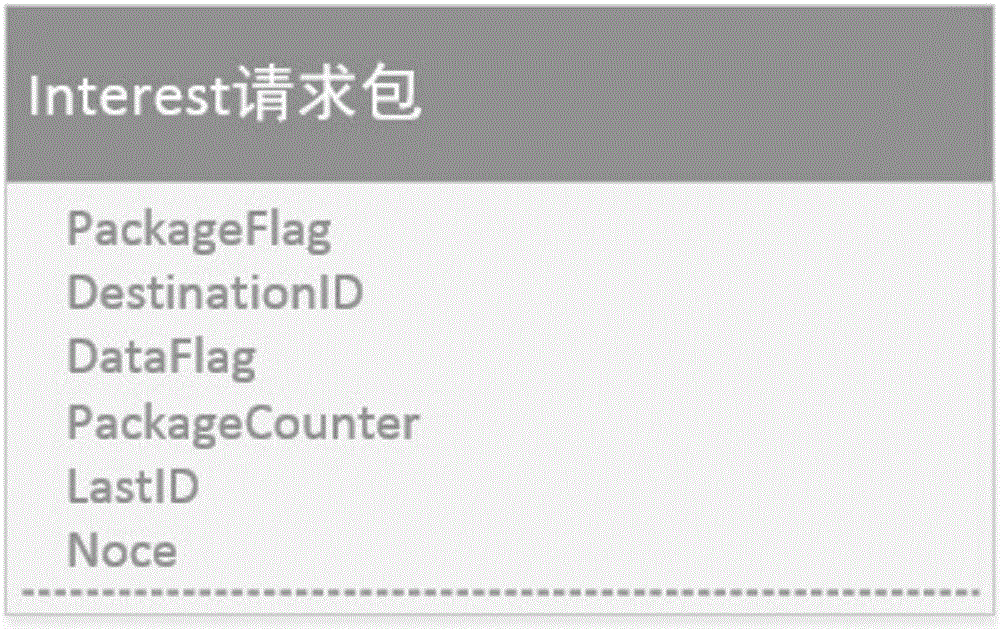
[0232] Step 6: The base station sends an interest request packet, where the interest packet includes the type of data packet, the requested destination node, the requested data type, the batch number of the requested data packet, the last hop node number of this node, and a random number ;Where the data packet type is 1, which means it is a request data packet; the request ...

Embodiment 2

[0252] The difference between this embodiment and that described in Embodiment 1 is that in step 7-1, if node 1 receives the interest sent by the base station, it performs a ContentStore query and finds that the interest exists, and then executes step 7-2.

[0253] Step 7-2: Node 1 directly sends the Data packet back to the base station node number, and the whole process ends.

[0254] Table 2 is the simulation experiment comparison of this scheme and traditional scheme in embodiment 2

[0255]

[0256] It can be seen from Table 2 that the energy consumption of this solution is about (300-201) / 300*100%=33%

Embodiment 3

[0258] The difference between this embodiment and that described in Embodiment 1 is that in step 8-1, if node 1 sends the interest request packet to the PendingInterestTable of this node for query and finds that interest exists, then step 8-2 is performed.

[0259] Step 8-2: Node 1 stores the previous hop node number stored in the interest (for example, the node number of the base station) in the IncomingQueue queue of the corresponding item of interest in the PendingInterestTable, and the delivery of the interest request packet is completed, and the whole process ends.


PUM


Abstract

The invention discloses a data naming-centered wireless sensor network asynchronous sleep scheduling method. According to the technical scheme of the invention, in the network of a wireless sensor, a network framework for naming data is realized and the environment of the network is deployed. Meanwhile, an issuing request is sent out in an internet request packet and a data information packet is returned. The sleep scheduling of nodes is conducted periodically and the retransmission mechanism is performed. Based on the structure of the network, the networks of the sensor at different rates can be unified. Meanwhile, a corresponding asynchronous sleep scheduling policy is provided. In this way, the purposes of expanding the size, conducting the field deployment and reducing the energy consumption of a battery can be realized.

Description


Claims


Application Information

Patent Timeline
Owner NORTHWEST UNIV
Why Eureka
Try Eureka