
Network filter

A network filter and housing technology, applied in the field of electrical signal transmission, can solve the problems of PIN pin and coil lead wire disconnection, high-voltage processing cost, continuous welding, etc., to save solder, labor and processing costs, and simple process Effect

Active Publication Date: 2015-11-18
MIANYANG HI TECH ZONE HONGQIANG TECH
View PDF6 Cites 4 Cited by
  • Summary
  • Abstract
  • Description
  • Claims
  • Application Information

AI Technical Summary

Problems solved by technology

[0003] Aiming at the above-mentioned deficiencies in the prior art, the present invention provides a network filter, which solves the problems of disconnection, continuous welding, high voltage and high processing cost that are easy to occur when the PIN pin and the coil lead wire of the current network filter are connected by winding wires.

Method used


Image

  • Network filter
  • Network filter
  • Network filter

Examples


Embodiment Construction

[0021] The present invention will be further described below in conjunction with accompanying drawing:

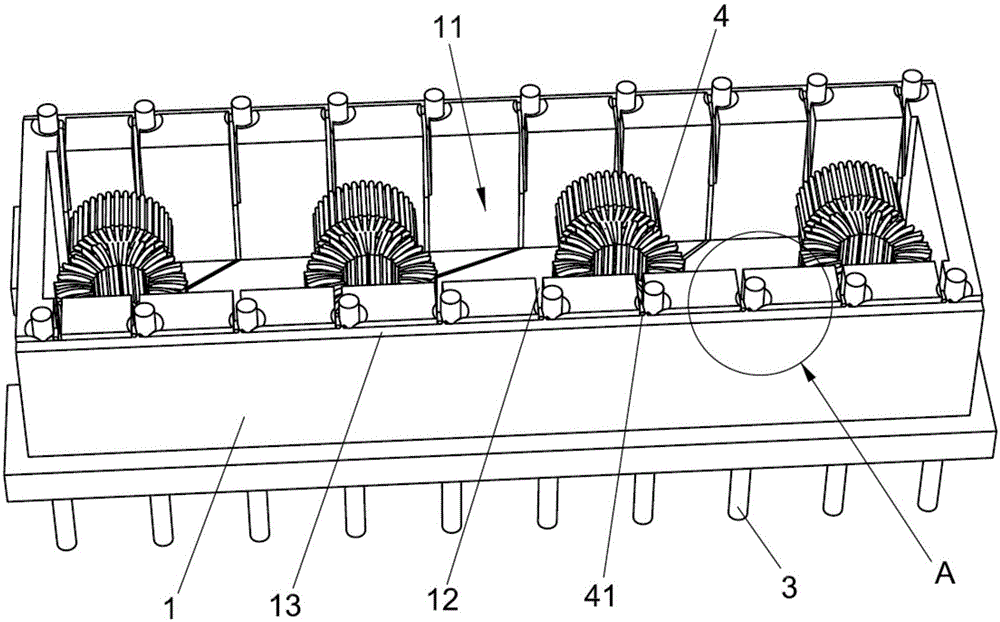
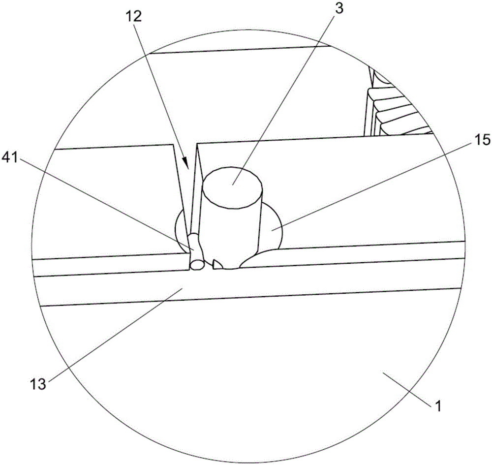
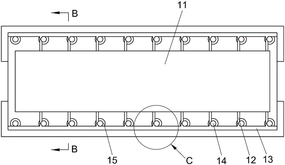
[0022] The present invention provides a network filter, as attached figure 1 As shown, it includes a housing 1 , a PIN needle 3 and an inductance coil 4 . The housing 1 is provided with a groove 11, and the inductance coil 4 is arranged in the groove 11. The housing 1 on both sides of the groove 11 is provided with a clamping groove 12 communicating with the groove 11, and the coil lead wire 41 of the inductance coil 4 is arranged In the wire holding slot 12 , the width of the wire holding slot 12 is larger than the diameter of the coil lead wire 41 . An installation through hole 14 is provided on the edge of the wire clamping slot 12 , the PIN pin 3 is fixedly connected in the installation through hole 14 , and the PIN pin 3 penetrates the housing 1 . The number of PIN needles 3 is the same as the number of coil lead wires 41 .

[0023] as attached figure 2 As shown, ...


PUM


Abstract

The invention discloses a network filter. The network filter comprises a shell, PINs and induction coils, a grooves is formed in the shell, the induction coils are arranged in the groove, multiple wire clamping grooves communicated with the groove are formed in the parts, at the two sides of the groove, of the shell, and coil lead wires of the induction coils are arranged in the wire clamping grooves. Multiple installation through holes are formed in the edge of each wire clamping groove, and the PINs are fixedly connected in the installation through holes. The ends of the coil lead wires are pressed tightly and fixed through the PINs and the inner walls of the wire clamping grooves, and the PINs and the coil lead wires are connected by way of soldering. A wire cutting step used for cutting away unnecessary coil lead wires is arranged at the edge of the shell. According to the network filter, the connection mode that the ends of the coil lead wires are pressed tightly and fixed through the PINs and the inner walls of the wire clamping grooves is adopted, the conventional wire winding connection mode is substituted, the process becomes simple, manpower and processing cost are saved, problems that originally, tweezers are used, so that surface paint on coil lead wires is prone to being damaged, and the coil lead wires are prone to being broken due to clamping are avoided, the electrical performance is improved, and the product qualified rate is raised.

Description

technical field [0001] The invention belongs to the technical field of electric signal transmission, and in particular relates to a network filter. Background technique [0002] The traditional network filter PIN pin and coil lead wire connection method adopts the winding type. The PIN pin is provided with a concave-convex bayonet and a card slot. The coil lead wire is wound on the PIN pin concave-convex groove. Pass. However, using this method of operation, the process is complex and cumbersome, and the operation is difficult. In the process of winding the wire, the tightness of the winding wire of the coil lead wire needs to be controlled. The tweezers used for winding the wire need to be polished so that the enameled wire paint is not damaged during the winding process. , otherwise it will cause bad high voltage, and too sharp tweezers will cause the coil lead to break. The traditional wire winding process makes the solder joints of the PIN feet larger, and the amount o...

Claims


Application Information

Patent Timeline
Patent Type & Authority Applications(China)
IPC IPC(8): H01F27/29H01F27/30H01F17/00
Inventor 余代春王强
Owner MIANYANG HI TECH ZONE HONGQIANG TECH
Learn More