Eureka AIR delivers breakthrough ideas for toughest innovation challenges, trusted by R&D personnel around the world.

Metal reflective insulation layer for nuclear grade equipment and pipelines

A technology of metal reflection type and thermal insulation layer, which is applied in the direction of pipeline protection, thermal insulation, mechanical equipment, etc., can solve the problems of thermal insulation effect, that is, poor thermal insulation effect, and achieve the effect of improving thermal insulation effect, improving economy and reducing the number of layers

Active Publication Date: 2017-10-13
NUCLEAR POWER INSTITUTE OF CHINA
View PDF2 Cites 0 Cited by
  • Summary
  • Abstract
  • Description
  • Claims
  • Application Information

AI Technical Summary

Problems solved by technology

[0003] The existing insulation layer includes an insulation outer box and a reflective foil, such as the patent US3904379A, which invented a sleeve-type metal reflective insulation plate structure, and the reflective foil adopts a corrugated shape; another example is the patent CN1159062A provides a The metal insulation layer of corrugated reflective foil; CN203131332U also provides a metal thermal insulation layer of corrugated reflective foil, and its thermal insulation effect is not good

Method used


Image

  • Metal reflective insulation layer for nuclear grade equipment and pipelines
  • Metal reflective insulation layer for nuclear grade equipment and pipelines
  • Metal reflective insulation layer for nuclear grade equipment and pipelines

Examples


Embodiment 1

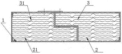
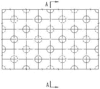
[0029] Such as Figure 1 to Figure 5 A metal reflective insulation layer for nuclear-level equipment and pipelines is shown. The reflective foil of this solution is arranged in the thermal insulation outer box 1, and the reflective foil includes the first reflective foil 2 and the second reflective foil 3 On the first reflective foil 2, hemispherical dimples I 21 and convex bubbles I arranged at intervals are pressed, and on the second reflective foil 3, hemispherical dimples with a diameter larger than dimples I 21 are also pressed. The diameters of II31 and convex II, concave II31 and convex II are larger than those of concave I21 and convex I, forming a structure of "one shallow and one deep" alternately stacked, which can better suppress the reflection of adjacent two layers Air convection heat exchange between the foils improves the heat preservation effect, the diameter of the concave bubble II 31 and the convex bubble II is larger, and the distance between the bottom of...

Embodiment 2

[0032] Such as Figure 1 to Figure 5 The metal reflective insulation layer for nuclear-level equipment and pipelines shown in this embodiment is optimized on the basis of the above embodiments, that is, the concave bubble I 21 and the convex bubble I are on the first reflective foil 2 arranged in a matrix.

[0033] The concave bubbles II 31 and convex bubbles II are arranged in a matrix on the second reflective foil 3 .

[0034]On the second reflective foil, the concave cell II 31 and the convex cell II with a hemispherical radius of SR5mm~SR15mm are pressed, and the layer height H after molding is 10mm to 30mm, that is, the height between the bottom of the concave cell II 31 and the top of the convex cell II is 10mm to 30mm; according to the thickness of the insulation layer and the insulation performance requirements, dimples II 31 and convex bubbles II with different diameters can be made to adjust the layer spacing and number of layers of adjacent reflective foils in the ...


PUM


Abstract

The invention discloses a metal reflective thermal insulation layer for nuclear-level equipment and pipelines, which comprises a thermal insulation outer box and reflective foils arranged in the thermal insulation outer box, and the reflective foils include first reflective foils arranged at intervals from each other and the second reflective foil, the first reflective foil is pressed with hemispherical dimples I and convex bubbles I arranged at intervals, and the second reflective foil is also pressed with hemispherical and diameter Concave cell II and convex cell II, which are larger than concave cell I, have better thermal insulation performance.

Description

technical field [0001] The invention relates to heat preservation equipment for nuclear grade equipment and pipelines, in particular to a metal air cavity reflective heat insulation layer for nuclear power plants and nuclear power plant equipment and pipelines. Background technique [0002] When nuclear-grade equipment and pipelines are in normal operation, high-temperature and high-pressure media flow inside. It is necessary to install an insulation layer on the outer surface of the equipment and pipelines for heat insulation, so as to reduce heat loss as much as possible, reduce the temperature difference between the inside and outside of the equipment and pipelines, and reduce the temperature difference. Equipment thermal stress, while protecting adjacent equipment. [0003] The existing insulation layer includes an insulation outer box and a reflective foil, such as the patent US3904379A, which invented a sleeve-type metal reflective insulation plate structure, and the r...

Claims


Application Information

Patent Timeline
Patent Type & Authority Patents(China)
IPC IPC(8): G21C11/08F16L59/08
CPCF16L59/08G21C11/083Y02E30/30
Inventor 周高斌罗英王小彬陈海波杨敏邱天谢国福李玉光付强马姝丽张亚斌尹祁伟李长香王眉杨立才董元元曾鹏
Owner NUCLEAR POWER INSTITUTE OF CHINA
Why Eureka
Eureka Blog
Learn More