
Centralized dust removal device for cyclone dust removers and waste heat boilers

A technology of cyclone dust collector and waste heat boiler, which is applied in gas dedusting, chemical instruments and methods, liquid scrubbing gas purification, etc., can solve the problems of excessive dust in cyclone dust collector and waste heat boiler, meet environmental protection and safety requirements, reduce Pollution, the effect of solving large dust

Inactive Publication Date: 2015-11-18
QITAIHE BAOTAILONG COAL CHEM IND
View PDF7 Cites 0 Cited by
  • Summary
  • Abstract
  • Description
  • Claims
  • Application Information

AI Technical Summary

Problems solved by technology

[0003] The present invention aims to solve the problem of excessive dust in existing cyclone dust collectors and waste heat boilers, and provides a centralized dust removal device for cyclone dust collectors and waste heat boilers

Method used


Image

  • Centralized dust removal device for cyclone dust removers and waste heat boilers

Examples


specific Embodiment approach 1

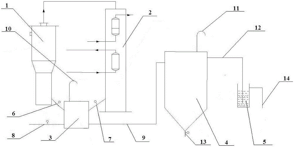
[0010] Specific Embodiment 1: In this embodiment, a device for centralized dust removal of cyclone dust collectors and waste heat boilers includes a dust collector 3, a dust collection tank 4 and a circulating water tank 5; the dust collector 3 communicates with the first discharge pipe 6 The cyclone dust collector 1 is connected, and the dust collector 3 is connected to the waste heat boiler 2 through the second discharge pipe 7. The bottom of the dust collector 3 is provided with a nitrogen pipe 8, and the dust collector 3 is connected to the waste heat boiler 2 through the delivery pipe 9. The dust collection tank 4 is connected, and the top of the dust collector 3 is provided with a first vent pipe 10; the top of the dust collection tank 4 is provided with a second vent pipe 11, and the bottom of the dust collection tank 4 is provided with The third discharge pipe 13 , the dust collecting tank 4 is connected to the circulating water tank 5 through the first overflow pipe 12...

specific Embodiment approach 2

[0013] Embodiment 2: This embodiment differs from Embodiment 1 in that: the first overflow pipe 12 is arranged on the upper part of the dust collecting tank 4 . Others are the same as in the first embodiment.


PUM


Abstract

The invention relates to a centralized dust removal device for cyclone dust removers and waste heat boilers, which aims to solve the problem of overhigh dust in the existing cyclone dust removers and waste heat boilers. The centralized dust removal device for cyclone dust removers and waste heat boilers comprises a dust collector, a dust collection tank and a water circulating channel, wherein the dust collector is connected with the cyclone dust remover through a first discharge pipe; the dust collector is connected with the waste heat boiler through a second discharge pipe; the bottom of the dust collector is provided with a nitrogen pipe; the dust collector is connected with the dust collection tank through a delivery pipe; the top of the dust collector is provided with a first escape pipe; the top of the dust collection tank is provided with a second escape pipe; the bottom of the dust collection tank is provided with a third discharge pipe; the dust collection tank is connected with the water circulating channel through a first overflow pipe; and the water circulating channel is provided with a second overflow pipe. The centralized dust removal device is used for centralized dust removal for cyclone dust removers and waste heat boilers.

Description

technical field [0001] The invention relates to a centralized dust removal device for a cyclone dust collector and a waste heat boiler. Background technique [0002] The dust is too large and the temperature is high during the dust removal process of the cyclone dust collector and waste heat boiler. The surrounding area is an equipment area, which is also a flammable and explosive area. It is inconvenient for mechanical vehicles to enter, so the fine ash is not easy to send out of the boundary area. If it is directly discharged into the ditch, the difficult problem of ash discharge is solved; however, a large amount of fine ash is deposited in the ditch and the circulating pool, which is difficult to clean up, causing damage to the water pump itself, and the circulating water volume will also decrease, and it is easy to block the pipes and spraying devices , which has a greater impact on the cooling of the scrubber gas. Contents of the invention [0003] The present inven...

Claims


Application Information

Patent Timeline
IPC IPC(8): C10K1/02C10K1/08B01D45/18
CPCY02P20/129
Inventor 于庆波李军鄂佳欣范沄涛
Owner QITAIHE BAOTAILONG COAL CHEM IND
Learn More