Railway freight car self-adjusting bogie

A technology for railway freight cars and bogies, which is applied in the field of self-heightening bogies for railway freight cars, which can solve the problems of small bogie axle load, large height difference, and impact on driving safety, and achieve low transformation costs, simple structure, and automatic toned down effect

Active Publication Date: 2017-07-07
CRRC YANGTZE CO LTD
View PDF5 Cites 0 Cited by
  • Summary
  • Abstract
  • Description
  • Claims
  • Application Information

AI Technical Summary

Problems solved by technology

[0003] The first is the frame bogie, which mainly adopts the primary axle box suspension system. This type of bogie has the advantages of small unsprung mass and high critical speed, but the axle load of this type of bogie is small, which cannot meet the requirements of modern railways on large axles. The demand for heavy bogies, and the height difference between the empty car and the heavy car of this type of bogie is relatively large, so the coupler height difference between the empty car and the heavy car is likely to cause a coupler fracture accident and affect driving safety;
[0004] The second type is the three-piece bogie, which mainly adopts the central suspension system. This type of bogie has the advantages of heavy axle and low cost, but the height difference between the empty car and the heavy car is relatively large. In this way, the coupler height difference between the empty car and the heavy car is likely to cause a coupler fracture accident, which affects driving safety.
[0005] Therefore, the existing bogies have been difficult to meet the needs, and it is urgent to develop a new type of bogie that can automatically adjust the height.

Method used


Image

  • Railway freight car self-adjusting bogie
  • Railway freight car self-adjusting bogie
  • Railway freight car self-adjusting bogie

Examples


Embodiment Construction

[0046] The present invention will be further described in detail below in conjunction with the drawings and specific embodiments:

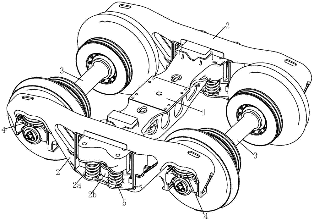
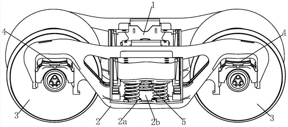
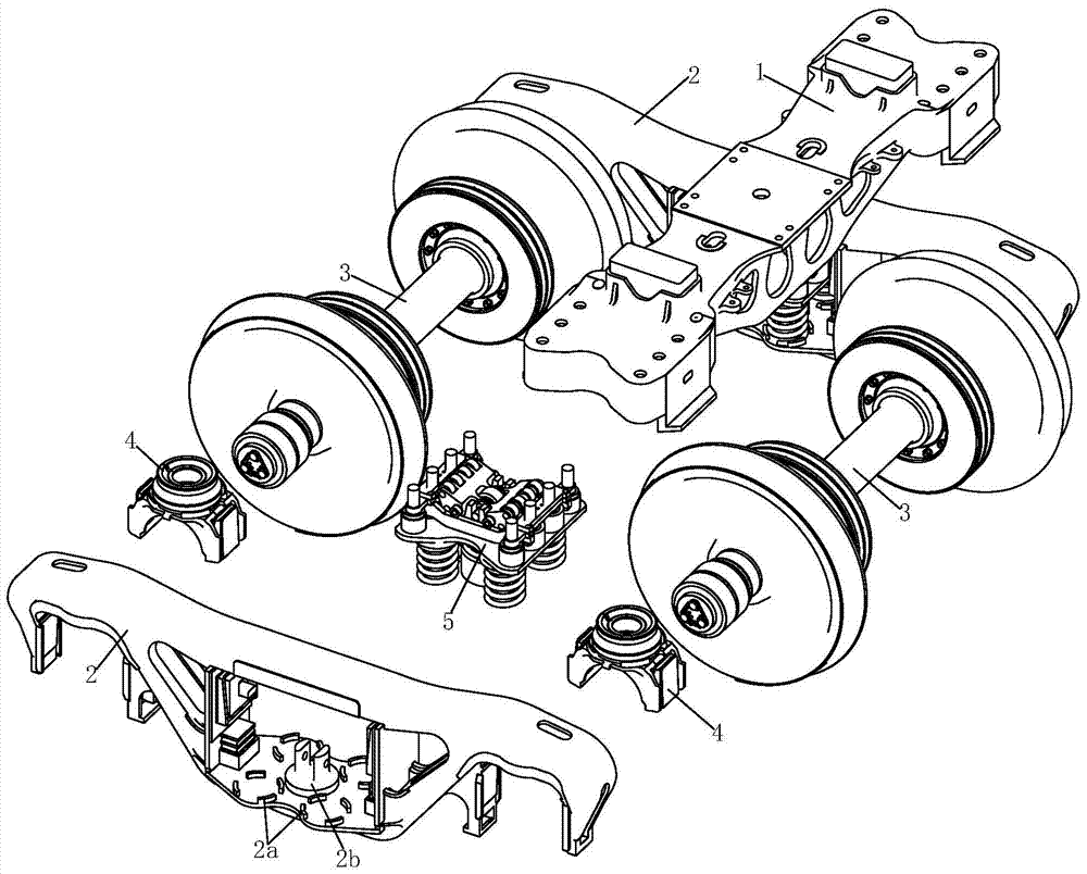
[0047] Such as figure 1 The shown self-elevating bogie of a railway freight car includes a bolster 1, a side frame assembly 2 and a wheel axle assembly 3. The two end guide frames of the side frame assembly 2 are supported on the axle assembly 3 through an axle box elastic positioning device 4 , There is a self-elevating device 5 between the two ends of the bolster 1 and the central frame of the side frame composition 2. The self-elevating device 5 includes a bearing support plate 5b installed on the bottom of the central frame through a bearing spring 5a, There are struts 5c on both sides of the supporting pallet 5b. The struts 5c are fitted with a taper sleeve assembly 5d. The supporting pallet 5b is superimposed with a middle pallet 5e. The two sides of the middle pallet 5e are respectively sleeved in the middle position. On the outer cone sleeve ...


PUM


Abstract

A self-heightening bogie for a railway freight car, the two ends of the side frame components are placed on the wheel shaft components, and a self-height adjustment device is provided between the bolster and the side frame components, and the self-height adjustment device is installed on the central side through a load spring. The supporting plate on the frame, there are struts on both sides of the supporting plate, the taper sleeve assembly is set on the support rod, the middle supporting plate is stacked on the supporting plate, and the two sides of the middle supporting plate are respectively sleeved on the outer cone of the taper sleeve assembly. Put it on, there is a limit frame on the top of the middle supporting plate, and the two sides of the limit frame are respectively set on the support rods. There is a pull rod inside, and the upper ends of the pull rods are respectively hinged with the hinged ends of the left crank and right crank. The free ends of the left crank and right crank are respectively provided with upper rollers and lower rollers. A limit roller is provided, and a return spring is provided under the middle supporting plate. The upper surface of the middle supporting plate is offset against the lower roller, the upper roller is offset against the inner surface of the bolster, and the bolster is covered on the support rod. Suitable for railway wagons.

Description

Technical field [0001] The invention relates to the field of railway freight car bogies, in particular to a railway freight car self-adjusting bogie. Background technique [0002] At present, heavy load and fast speed are the main directions for the development of railway freight cars. With the continuous improvement of railway freight car axle load and operating speed, the operating conditions of railway freight car bogies are more complicated, and the action force between wheels and rails continues to increase and accelerate The wear of the wheels and rails. The existing bogies mainly have two forms: [0003] The first type is a frame type bogie, which mainly adopts a series axle box suspension system. This type of bogie has the advantages of low unsprung mass and high critical speed. However, this type of bogie has a small axle weight, which cannot meet the requirements of modern railways for large axles. The demand for heavy bogies, and the height difference between empty and...

Claims


Application Information

Patent Timeline
Patent Type & Authority Patents(China)
IPC IPC(8): B61F5/04
Inventor 曹阳刘凤伟王宝磊姜瑞金徐勇严志雄神圣
Owner CRRC YANGTZE CO LTD
Why Eureka
Try Eureka