
Active interference elimination method in UFMC system

A technology of active interference cancellation and interference pairing, which is applied in baseband systems, transmission systems, multi-frequency code systems, etc., and can solve the problems of low efficiency of short burst communication, lax time-frequency calibration, and reduced signaling overhead.

Active Publication Date: 2015-11-11
ZHEJIANG UNIV
View PDF8 Cites 14 Cited by
  • Summary
  • Abstract
  • Description
  • Claims
  • Application Information

AI Technical Summary

Problems solved by technology

Even so, OFDM has great disadvantages: First, the higher side lobe level
It has the following characteristics: a) it has a low side lobe level, and the interference between subcarriers is small; b) it can achieve a time-frequency efficiency of 1, but the premise is that the filter length tends to be infinite, which will bring new problems: The rising and falling time of the filter will make the efficiency of short burst communication very low, and short burst is very important for future MTC (Machine Type Communication); c) The OQAM mechanism adopted is not directly compatible with all types of MIMO systems; d ) Theoretically, FBMC has good characteristics, but when it is configured, it is actually not feasible
It has the following characteristics: a) supports segmented spectrum communication; b) compared with OFDM, the spectrum sidelobe level is dozens of dB less, which is very low; c) it has a higher resistance to time-frequency offset and inter-carrier interference Robustness; d) Since the time-frequency calibration is not strict, the signaling overhead is reduced, which also introduces many new options for access; e) The key lies in the design of the filter, which has a certain complexity

Method used


Image

  • Active interference elimination method in UFMC system
  • Active interference elimination method in UFMC system
  • Active interference elimination method in UFMC system

Examples


Embodiment Construction

[0091] The present invention will be described in further detail below in conjunction with the accompanying drawings and specific implementation examples.

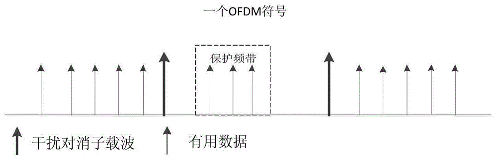
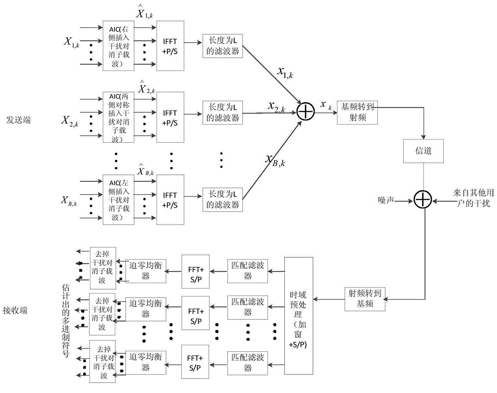
[0092] The introduction background of AIC is attached figure 1 As shown, the schematic diagram of the combination of UFMC and AIC is shown in the attached figure 2 Shown, the schematic diagram of the transceiver of the inventive method is as attached image 3 shown.

[0093] The active interference elimination method in a kind of UFMC system of the present invention, concrete implementation steps are as follows:

[0094] 1) It is assumed that the interference caused to the 4th sub-band comes from the 3rd sub-band and the 5th sub-band, and the 3rd, 4th and 5th sub-bands are treated as one arrangement, and the sub-carrier labels occupied by the three sub-bands are from From left to right: [7:18], [25:36] and [43:54].

[0095] 2) The original bit stream performs multi-ary modulation mapping:

[0096] 2.1) The original b...


PUM


Abstract

The invention discloses an active interference elimination method in a UFMC system. The method comprises the steps that a transmission end adds a certain number of interference cancellation subcarriers at two sides of sub-bands symmetrically through a blank space between sub-bands of the UFMC system, enables raw data information and modulation data of the interference cancellation subcarriers to serve as new data information, and carries out modulation, filtering and transmission through the UFMC system, wherein the first sub-band and the last sub-band only operate at one side; a receiving end carries out time domain windowing preprocessing and serial-to-parallel conversion at first, then carries out FFT transformation through a filter matched with the transmission side, and finally obtains a new estimation value of data information through a zero-forcing equalizer, and recovers the raw data information after removing the modulated data of the interference cancellation subcarriers employed by all sub-bands. The method maintains the good properties of the UFMC system and enables the effect of interference inhibition between the sub-bands of the UFMC system through the combination of the UFMC with active interference cancellation, thereby improving the error bit ratio of the system, and improving the communication quality.

Description

technical field [0001] The invention relates to the field of wireless communication, in particular to an active interference elimination method in a UFMC system. Background technique [0002] As we all know, LTE and its current evolution form and WiFi all use OFDM as the basic signal format for carrying data. OFDM is currently the most important multi-carrier modulation technology. OFDM divides the entire channel into N sub-channels through N sub-carriers for parallel transmission of information. It mainly has the following advantages: First, high spectrum utilization. Not only there is no guard frequency band between each sub-channel of OFDM, but also the side lobes of the signal spectrum between adjacent channels overlap each other. In addition, each sub-channel of OFDM can adopt different multi-ary modulation schemes, which further improves the spectral efficiency of the system. Second, the implementation process is relatively simple. Modulation and demodulation can b...

Claims


Application Information

Patent Timeline
Patent Type & Authority Applications(China)
IPC IPC(8): H04L25/03H04L27/26
CPCH04L25/0216H04L25/03006H04L25/03821H04L27/2607H04L27/2647H04L27/2678
Inventor 张朝阳王红王超张昱王献斌罗茜倩
Owner ZHEJIANG UNIV
Learn More