
A smart photovoltaic module multifunctional junction box

A photovoltaic module and multi-functional technology, applied in photovoltaic power generation, photovoltaic modules, electrical components, etc., can solve the problems of high labor and material cost, damaged power generation performance, and impact on diode life, so as to reduce operation and maintenance costs and avoid wear and tear. and destruction, the effect of reducing manpower

Active Publication Date: 2017-04-12
JA SOLAR TECH YANGZHOU +1
View PDF9 Cites 0 Cited by
  • Summary
  • Abstract
  • Description
  • Claims
  • Application Information

AI Technical Summary

Problems solved by technology

[0003] With the continuous improvement of the power of photovoltaic power generation components in recent years, and the continuous improvement of the miniaturization requirements of the junction box based on cost considerations, the power dissipated by the bypass diode in the junction box of the installation and the module is increasing under the bypass working state. The operating temperature of the diode is getting higher and higher, and the life of the diode is greatly affected by working at a high temperature for a long time
In addition, because the external cables of the junction box are often dragged and plugged, and exposed to the outdoors, the cable interface is also prone to breakage or falling off.
These problems have nothing to do with the performance of the module itself, but will cause the output to be blocked and the power generation performance to be impaired
When this phenomenon occurs, we usually need to replace the entire module, which has a high cost of manpower and material resources, and the process of disassembly and transportation will also cause unnecessary damage to the module itself, which will bring cost losses to the maintenance of the power station and the module supplier.

Method used


Image

  • A smart photovoltaic module multifunctional junction box
  • A smart photovoltaic module multifunctional junction box
  • A smart photovoltaic module multifunctional junction box

Examples


Embodiment 1

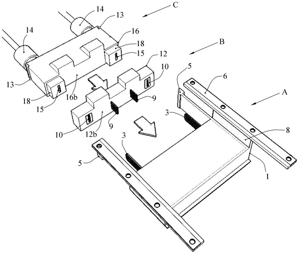
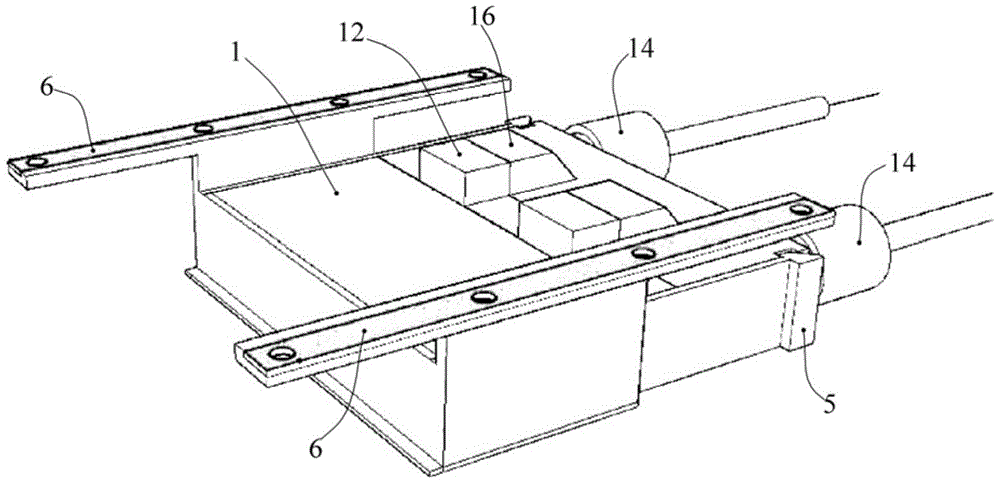
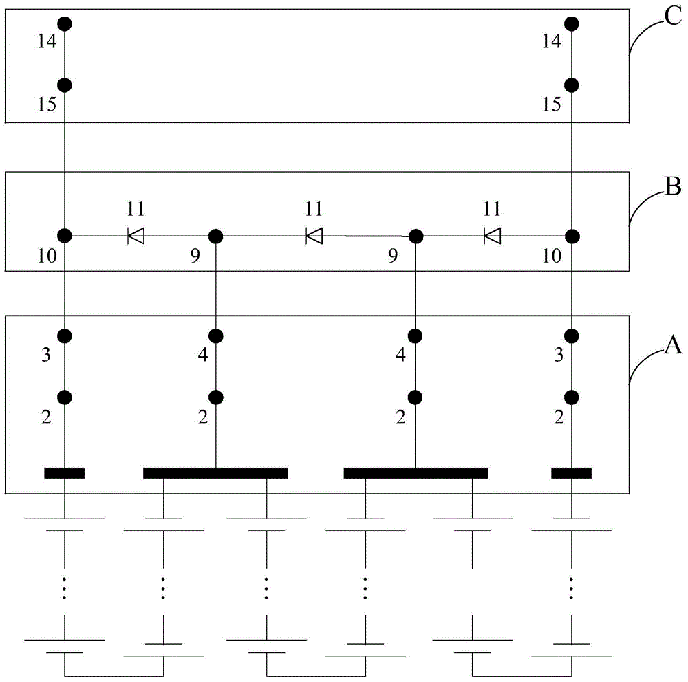
[0063] Such as Figure 1-1 to Figure 4As shown, the smart photovoltaic module multifunctional junction box according to Embodiment 1 of the present invention can be used to connect three strings of solar cell strings, which include a horizontal base module A, a horizontal diode module B and a horizontal cover module C.

[0064] The above-mentioned horizontal base module A is provided with a horizontal base insulating shell 1, four conductive posts 2 installed in the horizontal base insulating shell 1, two horizontal base conductive inserts 3 and two horizontal base conductive inserts. Holes 4, wherein, the bottom surface of the horizontal base insulating shell 1 is provided with openings 7 for introducing photovoltaic module bus bars, two horizontal base conductive inserts 3 and two horizontal base conductive jacks 4 are respectively connected with four The conductive columns 2 are electrically connected in a one-to-one correspondence, and the two horizontal base conductive in...

Embodiment 2

[0077] Such as Figure 5-1 to Figure 8 As shown, the multifunctional junction box of the smart photovoltaic module according to the second embodiment of the present invention can be used to connect three strings of solar cell strings, which include a vertical base module VA, a vertical diode module VB and a vertical cover module VC.

[0078] The above-mentioned vertical base module VA is provided with a vertical base insulating shell V1 and four conductive pillars 2 installed in the vertical base insulating shell V1, two vertical long base conductive inserts V3 and two vertical short Type base conductive insert V4, wherein, the bottom surface of the vertical base insulating shell V1 is provided with an opening 7 for introducing the bus bar of the photovoltaic module, two vertical long base conductive inserts V3 and two vertical short bases The conductive inserts V4 are respectively electrically connected to the four conductive pillars 2 in a one-to-one correspondence and are e...

Embodiment 3

[0091] Such as Figure 9 As shown, the multifunctional junction box of the smart photovoltaic module in the third embodiment of the present invention is basically the same as the first embodiment, and their difference is that the multifunctional junction box of the smart photovoltaic module in the third embodiment also includes a horizontal smart electronic module D, The horizontal intelligent electronic module D is provided with a horizontal intelligent electronic module insulating housing 19 and an intelligent electronic circuit unit installed in the horizontal intelligent electronic module insulating housing 19 and two horizontal intelligent electronic modules conduct electricity. Socket holes 20, wherein the intelligent electronic circuit unit is electrically connected to the conductive socket holes 20 of the two horizontal intelligent electronic modules respectively, and the conductive socket holes 20 of the two horizontal intelligent electronic modules are all in the hori...


PUM


Abstract

The invention discloses an intelligent photovoltaic component multifunctional junction box which at least comprises a substrate module, a diode module and a cover plate module. The substrate module, the diode module and the cover plate module can be freely spliced and split. When the substrate module, the diode module and the cover plate module are integrally spliced, a diode insulating shell is arranged between a substrate insulating shell and a cover plate insulating shell, and all the conductive plugging connectors of the substrate module, the diode module and the cover plate module are enabled to be plugged in an adaptive manner so that a circuit structure capable of providing a power output protection function to a photovoltaic component can be formed by the electrical parts in the substrate module, the diode module and the cover plate module, and the substrate module, the diode module and the cover plate module are enabled to be stably spliced together. The junction box is easy to maintain, and maintenance manpower, material resource and time loss can be reduced so that operation and maintenance cost of a photovoltaic power station can be greatly reduced.

Description

technical field [0001] The invention relates to a multifunctional junction box of an intelligent photovoltaic module, which belongs to the technical field of solar battery modules. Background technique [0002] The solar module junction box is the direct part of the module performance output, generally composed of a box body, a box cover, a bypass diode set in the box body, a metal conductor, wires and cables, and cable connectors. Among them, the function of the bypass diode is that when the hot spot effect of the cell cannot generate electricity, it acts as a bypass, allowing the current generated by other cells to flow out of the diode, so that the solar power generation system continues to generate electricity, and will not be caused by a cell. The power generation circuit is blocked due to the problem. Except for the box cover, the traditional junction box is integrated as a whole. After connecting with the bus bar leading out of the module, it is fixed on the back of ...

Claims


Application Information

Patent Timeline
Patent Type & Authority Patents(China)
IPC IPC(8): H02S40/34
CPCY02E10/50
Inventor 周艳方特尔德·加利特夫单伟
Owner JA SOLAR TECH YANGZHOU
Learn More