
Drill rig support frame for coal mine

A technology for drilling rigs and coal mines, applied in drilling equipment, earthwork drilling, support devices, etc., can solve the problems of large space occupation, inflexible adjustment of pitch angle, and inability to be used independently, saving space and avoiding rod change interference , the effect of improving positional stability

Inactive Publication Date: 2015-11-11
HENAN UNIV OF SCI & TECH
View PDF8 Cites 1 Cited by
  • Summary
  • Abstract
  • Description
  • Claims
  • Application Information

AI Technical Summary

Problems solved by technology

[0002] When coal mine drilling rigs are operating underground in coal mines, due to work needs, the location needs to be constantly changed. Even at the same location, the angle and height of the drilling holes need to be changed from time to time. Most of the prior art coal mine drilling rigs do not have With the function of 360° rotation, the adjustment of the pitch angle is not flexible enough
When the position of the drill hole needs to be adjusted, the position of the entire device needs to be adjusted to achieve the desired position, which is time-consuming and laborious to work
[0003] In addition, the supporting devices of existing drilling rigs are all integrated with the body of the drilling rig, and the structure is rigid and cannot be used independently, which cannot meet the needs of narrow spaces
[0004] The support device of some drilling rigs uses supports, but there are four supports, which takes up a lot of space, and the four guide supports are easy to interfere with the rod changing action, which is inconvenient

Method used


Image

  • Drill rig support frame for coal mine
  • Drill rig support frame for coal mine
  • Drill rig support frame for coal mine

Examples


Embodiment Construction

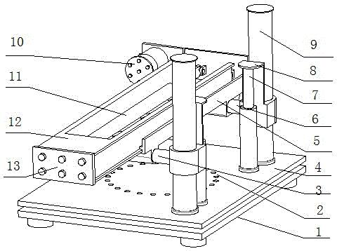
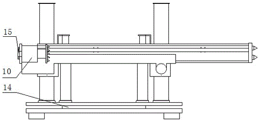
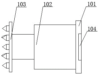
[0016] As shown in the figure, a coal mine drilling rig support includes a chassis 1, a turntable bearing 14 and a support body, the support body is arranged on the base 1 through the turntable bearing 14, and the support body includes a The rotating platform 4, the corresponding positions of the rotating platform 4 and the base 1 are provided with positioning holes 2, and the upper end surface of the rotating platform 4 is provided with two guide support columns 9, and each guide support column 9 is provided with a pipe buckle 8, in which The pipe buckle 8 on one side is provided with front beam 3, and the pipe buckle 8 on the other side is provided with back beam 6, and described front beam 3 and back beam 6 are fixedly connected with corresponding pipe buckle 8 respectively, between front beam 3 and The back beam 6 is provided with a slide seat 5 for placing the guide rail 12. The front beam 3 passes through the holes on the two side walls of the slide seat 5 and is connecte...


PUM


Abstract

The invention relates to a drill rig support frame for a coal mine. The drill rig support frame comprises an underpan, a turntable bearing and a support frame body, wherein the support frame body is arranged on a base through the turntable bearing; the support frame body comprises a rotating platform connected with the turntable bearing; positioning holes are formed in the corresponding positions of the rotating platform and the base; the upper end surface of the rotating platform is provided with two guide support posts; a pipe buckle is arranged on each guide support post; a back support device is arranged on a slide seat; a front support ground gripping element is arranged on a guide rail; and a front support telescopic hydraulic cylinder for pushing the guide rail is arranged inside the guide rail. The drill rig support frame has the beneficial effects that the drill rig support frame can rotate for 360 degrees; the two guide support posts are used, so that the space is saved, and the rod changing interference caused by four guide support posts is avoided; the front support ground gripping element and the back support device are used, so that the front part and the back part are propped and supported, and the position stability of a drill rig during the thrust hole drilling can be improved; and the drill rig support frame is particularly suitable to be used in a narrow space of a coal mine tunnel.

Description

technical field [0001] The invention relates to a drill truck used in coal mines, in particular to a drill truck bracket used in coal mines. Background technique [0002] When coal mine drilling rigs are operating underground in coal mines, due to work needs, the location needs to be constantly changed. Even at the same location, the angle and height of the drilling holes need to be changed from time to time. Most of the prior art coal mine drilling rigs do not have With the function of 360° rotation, the adjustment of pitch angle is not flexible enough. When the position of the drill hole needs to be adjusted, the position of the entire device needs to be adjusted to reach the desired position, which is time-consuming and laborious. [0003] In addition, the supporting devices of existing drilling rigs are all integrally produced with the body of the drilling rig, and the structure is rigid, which cannot be used independently and cannot meet the needs of narrow spaces. ...

Claims


Application Information

Patent Timeline
Patent Type & Authority Applications(China)
IPC IPC(8): E21B15/00E21B7/02
Inventor 张明柱张凯吴鑫
Owner HENAN UNIV OF SCI & TECH
Learn More