
Punch forming method and punch forming die for corrugated metal foil

A stamping forming and mold technology, which is applied in the metal corrugated foil stamping forming method and stamping forming mold field, can solve the corrugated foil size and mechanical properties are not good, it is difficult to achieve high amplitude forming, high bending ratio and other problems, Achieve good dimensional consistency, solve the effect of easy fracture and stable mechanical properties

Active Publication Date: 2015-11-11
SHENZHEN CANSINGA TECH CO LTD
View PDF5 Cites 4 Cited by
  • Summary
  • Abstract
  • Description
  • Claims
  • Application Information

AI Technical Summary

Problems solved by technology

[0005] In view of the deficiencies in the prior art above, the purpose of the present invention is to provide a metal corrugated foil stamping method and its stamping mold, aiming to solve the problem of the size and size of the corrugated foil formed by the existing metal corrugated foil forming method Poor mechanical properties, difficulty in high-amplitude forming, short pitch, and high bending ratio

Method used


Image

  • Punch forming method and punch forming die for corrugated metal foil
  • Punch forming method and punch forming die for corrugated metal foil
  • Punch forming method and punch forming die for corrugated metal foil

Examples


Embodiment Construction

[0029] The invention provides a metal corrugated foil stamping forming method and a stamping forming mold thereof. In order to make the object, technical solution and effect of the present invention more clear and definite, the present invention will be further described in detail below with reference to the accompanying drawings and examples. It should be understood that the specific embodiments described here are only used to explain the present invention, not to limit the present invention.

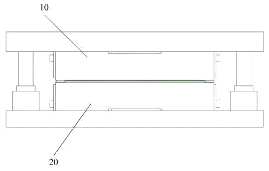
[0030] Such as figure 1 Shown is a metal corrugated foil stamping die according to a specific embodiment of the present invention.

[0031] The stamping mold shown includes: an upper rack die 10 and a lower rack die 20 .

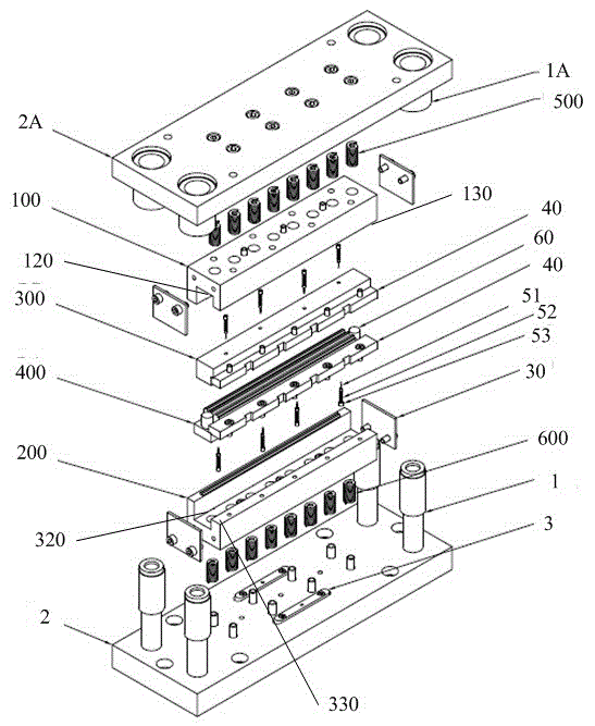
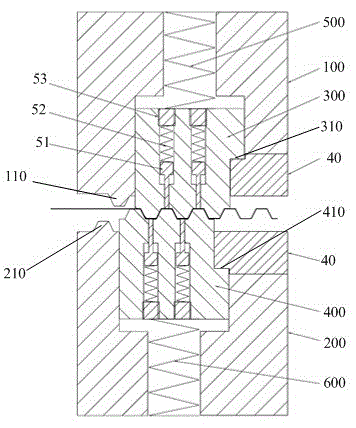
[0032] Among them, such as figure 2 and image 3 As shown, the upper rack mold 10 includes an upper forming tooth seat 100, an upper forming tooth 110 disposed on the upper forming tooth seat, and an upper shaping tooth rack 300 movable relative to the upper for...


PUM


Abstract

The invention provides a punch forming method and punch forming die for corrugated metal foil. The punch forming die comprises an upper rack die and a lower rack die, wherein the upper rack die comprises an upper forming tooth base, an upper forming tooth arranged on the upper forming tooth base and an upper shaping rack capable of moving relative to the upper forming tooth base; the upper forming tooth base is connected with the upper shaping rack through a limiting component so as to limit the upper shaping rack to the degree of freedom of moving in a die assembly direction; the lower rack die comprises a lower forming tooth base, a lower forming tooth and a lower shaping rack and has the same connection and structural position relation as the upper rack die; the upper forming tooth and the lower forming tooth are arranged asymmetrically; a sectional punch stroke is formed through the asymmetric motion of the upper shaping rack and the lower shaping rack during a die assembly process in combination with the corresponding forming teeth; and the sectional punch stroke comprises a first punch stroke for punching a material strip to bend the material strip to one side and a second punch stroke for punching the material strip to bend the material strip to the other side.

Description

technical field [0001] The invention relates to the technical field of metal material forming, in particular to a metal corrugated foil stamping forming method and a stamping forming mold thereof. Background technique [0002] Metal corrugated foil is a kind of corrugated foil material, which is widely used in aerospace, national defense equipment, rail transit, automobile heat dissipation and other fields. For example, the metal honeycomb formed by stacking semi-regular hexagonal corrugated foils has the advantages of low density, low rigidity, strong impact resistance, and controllable compression deformation. ; At the same time, the superimposed structure of short-pitch and high-amplitude corrugated foils has the characteristics of strong heat dissipation, and can be widely used as heat sink materials in heat dissipation environments such as automobiles and air conditioners. [0003] The existing metal corrugated foil forming methods mainly include gear rolling forming m...

Claims


Application Information

Patent Timeline
Patent Type & Authority Applications(China)
IPC IPC(8): B21D13/02B21D37/10
Inventor 胡舜罗昌杰于文泽
Owner SHENZHEN CANSINGA TECH CO LTD
Learn More