Air purification device and air purification method
The technology of an air purification device and a generation device, which is applied in the field of air purification, can solve the problems of destroying the balance of the vector magnetic field and the spiral magnetic field, the increase of the concentration of dust and fine dust, and the destruction of the dust purification mechanism, etc., and achieves long effective purification time, simple structure, Enhance the effect of natural purification ability
- Summary
- Abstract
- Description
- Claims
- Application Information
AI Technical Summary
Problems solved by technology
Method used
Image
Examples
Embodiment 1
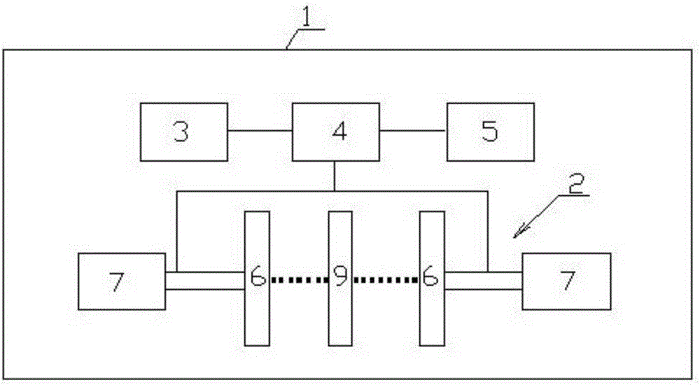
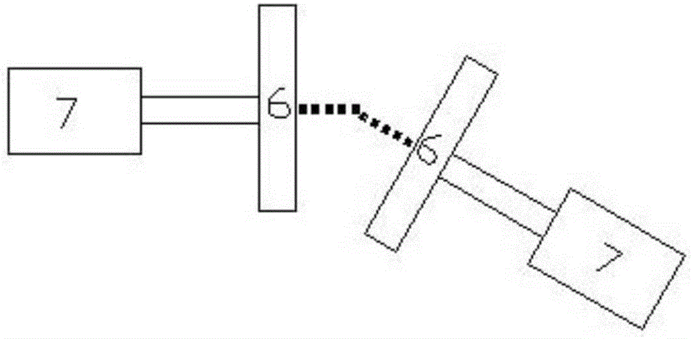
[0038] like figure 2 As shown, in this embodiment, the spiral magnetic field generating device 2 includes two magnetic energy units 6, and each magnetic energy unit 6 is respectively installed on a rotating mechanism 7, and the two rotating mechanisms 7 respectively drive the two magnetic energy units 6 to rotate in the same direction Or reverse rotation, one can also rotate and the other is stationary, as long as one magnetic energy unit 6 rotates, a helical magnetic field will be generated.
[0039] Rotary mechanism 7 can adopt any kind of rotating machine in the prior art, can adopt motor drive as drive source, and the output shaft of motor is connected with a shaft coupling, and magnetic energy unit 6 is fixedly connected with shaft coupling; Or, the output shaft of motor The linkage shaft is connected with the linkage shaft through the bearing and the shaft coupling, and the linkage shaft is connected with the magnetic energy unit 6 through the shaft coupling; or, the ro...
Embodiment 2
[0058] like Figure 4 As shown, the difference from Embodiment 1 is that there is one magnetic energy unit 6, and the magnetic energy unit 6 is fixedly installed on a rotating mechanism 7, and a helical field is generated by the rotation of one magnetic energy unit 6.
[0059] In order to further enhance the generated and released helical magnetic field energy, in this embodiment, it is preferable to install a counter object 10 on the opposite side of a magnetic energy unit 6, and the counter object 10 has the effect of enhancing the release of magnetic field energy. The counterpart 10 can be made of a magnetic material, preferably a ferromagnetic material. Same as the first embodiment, a spacer 9 can also be installed between the magnetic pole plane 8 of the magnetic energy unit 6 and the counterpart 10 to further strengthen the strength of the helical magnetic field.
[0060] Since only one magnetic energy unit 6 and one rotating mechanism 7 are used, when the area to be pu...
Embodiment 3
[0062] like Figure 5 As shown, the difference from Embodiment 1 and Embodiment 2 is that there are three magnetic energy units 6, and each magnetic energy unit 6 is installed on a rotating mechanism 7 respectively, and the three magnetic energy units 6 are arranged opposite to each other in a ring around the center line.
[0063] Between the three magnetic energy units 6 can be as Figure 5 As shown in the direct opposite arrangement, a spacer 9 can also be set at the center of the three magnetic energy units 6 in order to enhance the release effect of the magnetic field energy. At this time, the section of the spacer 9 can be triangular or circular. The three magnetic energy units 6 can rotate at any angle, any distance, and any rotation speed to generate the required helical magnetic field.
[0064] If the magnetic energy unit 6 is set to more than three situations, it is also arranged oppositely in a ring around the central line, and a spacer 9 is set at the center of a p...
PUM
 Abstract
Description
Claims
Application Information
 - R&D
- Intellectual Property
- Life Sciences
- Materials
- Tech Scout
- Unparalleled Data Quality
- Higher Quality Content
- 60% Fewer Hallucinations
Browse by: Latest US Patents, China's latest patents, Technical Efficacy Thesaurus, Application Domain, Technology Topic, Popular Technical Reports.
© 2025 PatSnap. All rights reserved.Legal|Privacy policy|Modern Slavery Act Transparency Statement|Sitemap|About US| Contact US: help@patsnap.com


