
Radio frequency cable assembly and magnetic resonance imaging system

A magnetic resonance imaging and radio frequency cable technology, which is applied in the direction of using nuclear magnetic resonance imaging system for measurement, magnetic resonance measurement, and magnetic variable measurement, etc., can solve the problems of inconvenient assembly of cables and traps, difficulty of radio frequency debugging, etc.

Pending Publication Date: 2021-12-21
UNITED IMAGING RES INST OF INNOVATIVE MEDICAL EQUIP
View PDF0 Cites 0 Cited by
  • Summary
  • Abstract
  • Description
  • Claims
  • Application Information

AI Technical Summary

Problems solved by technology

Traditional RF cable assemblies usually adopt the structure of winding the cable and fixing the wave trap on the cable. This structure is not only inconvenient to assemble the cable and wave trap, but also brings difficulty to RF debugging

Method used


Image

  • Radio frequency cable assembly and magnetic resonance imaging system
  • Radio frequency cable assembly and magnetic resonance imaging system
  • Radio frequency cable assembly and magnetic resonance imaging system

Examples


Embodiment Construction

[0032] The technical solutions in the embodiments of the present invention will be clearly and completely described below in conjunction with the accompanying drawings in the embodiments of the present invention. Obviously, the described embodiments are only part of the embodiments of the present invention, not all of them. Based on the implementation manners in the present invention, all other implementation manners obtained by persons of ordinary skill in the art without making creative efforts belong to the scope of protection of the present invention.

[0033] Unless otherwise defined, all technical and scientific terms used herein have the same meaning as commonly understood by one of ordinary skill in the technical field of the invention. The terminology used herein in the description of the present invention is only for the purpose of describing specific embodiments, and is not intended to limit the present invention. As used herein, the term "or / and" includes any and a...


PUM


Abstract

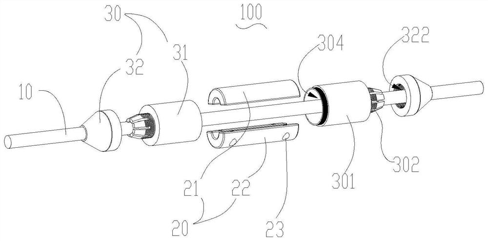
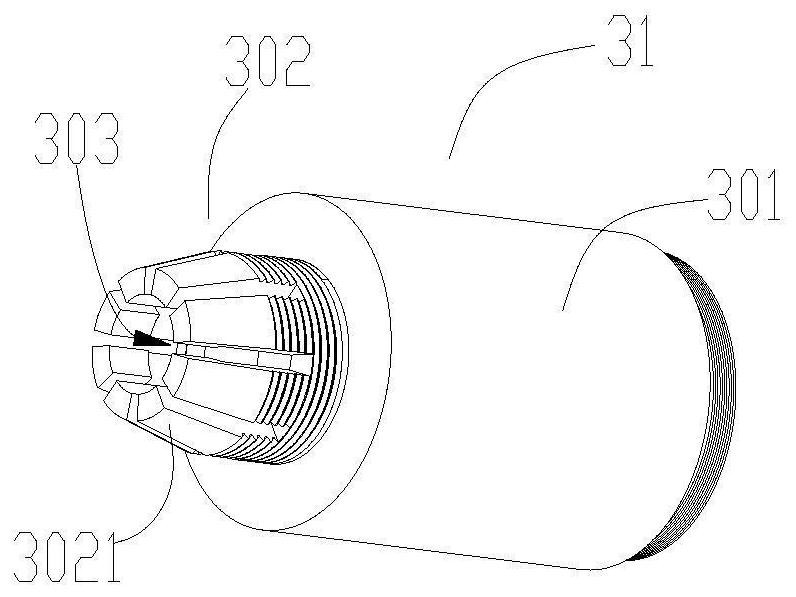
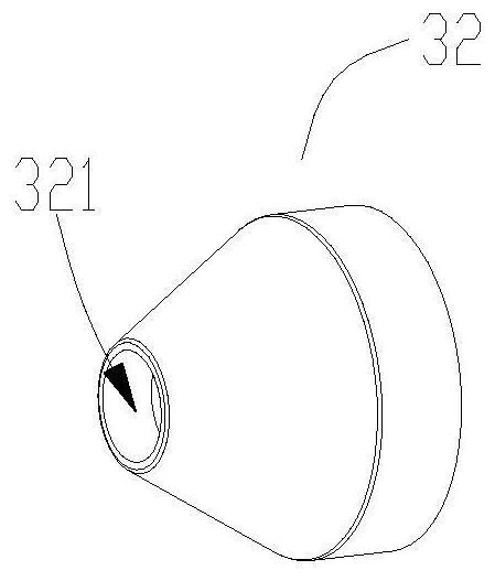
The invention provides a radio frequency cable assembly for a magnetic resonance imaging system and the magnetic resonance imaging system. The radio frequency cable assembly comprises a cable, a wave trap and a limiting and fixing unit, the wave trap is installed on the cable in a sliding mode, and the limiting and fixing unit comprises a sleeving part and a matching part which are relatively fixed; the sleeving part sleeves the wave trap, and the matching part has a locking state and a sliding state which can be converted; the matching part fixedly clamps the cable in the locking state so that the cable cannot slide relative to the sleeving part, and the matching part and the cable can slide relative to each other in the sliding state. The defect that a traditional radio frequency cable assembly needs to be wound with a cable is overcome, and the step of assembling the wave trap and the cable is simplified. When radio frequency debugging is carried out, the matching part is switched to a sliding state, so that fixation between the matching part and the cable can be relieved, and the wave trap can be driven to slide on the cable; and after radio frequency debugging is completed, the matching part is switched to a locking state, so that the matching part and the cable can be fixed again, and the wave trap is fixed on the cable.

Description

technical field [0001] The invention relates to the technical field of magnetic resonance imaging, in particular to a radio frequency cable assembly and a magnetic resonance imaging system. Background technique [0002] At present, radio frequency cable assemblies are commonly used in magnetic resonance imaging systems, and the radio frequency cable assemblies include cables and wave traps. In practical applications, it is necessary to perform radio frequency debugging on the radio frequency cable assembly according to the field strength of the imaging system and the radio frequency coil. Traditional radio frequency cable assemblies usually use a structure in which the cable is wound and the wave trap is fixed on the cable. This structure is not only inconvenient to assemble the cable and the wave trap, but also brings difficulty to radio frequency debugging. Contents of the invention [0003] In view of this, the present invention provides a radio frequency cable assembl...

Claims


Application Information

Patent Timeline
IPC IPC(8): G01R33/34G01R33/48
CPCG01R33/34G01R33/48
Inventor 钟继凡
Owner UNITED IMAGING RES INST OF INNOVATIVE MEDICAL EQUIP
Learn More