


Quick Research
Generate reliable direction feasibility study reports for your R&D in just a few steps.

Technical Q&A
Discover and master advanced knowledge NOW. Basics, ideas, possibilities, all at once.

Find Solutions
As an expert in R&D theories, this can generate solutions to your technical problems instantly.

Evaluate Feasibility
Analyze your overall solution with one click, know your potential R&D risks in advance.

Monitor Landscape
Get weekly tech updates, stay abreast of the latest tech innovations and key insights.
Special space shoes for astronauts
An astronaut, space technology, applied in the field of aerospace, can solve the problem of astronauts not being able to stand stably
- Summary
- Abstract
- Description
- Claims
- Application Information
AI Technical Summary
Problems solved by technology
Method used
Image


Examples
specific Embodiment approach 1
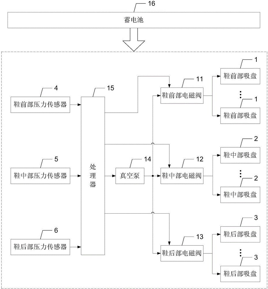
[0018] Specific embodiment one: the following combination Figure 1 to Figure 3 Illustrating this embodiment, the special space shoes for astronauts in this embodiment include m suction cups 1 at the front of the shoe, n suction cups at the middle of the shoe 2, k suction cups at the rear of the shoe 3, pressure sensors 4 at the front of the shoe, mid-shoe pressure sensor 5, rear-shoe pressure sensor 17, front-shoe solenoid valve 11, mid-shoe solenoid valve 12, rear-shoe solenoid valve 13, vacuum pump 14 and processor 15;
[0019] The m shoe front suction cups 1, the n shoe middle suction cups 2 and the k shoe rear suction cups 3 are respectively provided with the front, middle and rear regions of the lower bottom surface of the shoe;
[0020] The pressure sensor 4 at the front of the shoe, the pressure sensor 5 at the middle of the shoe and the pressure sensor 17 at the back of the shoe are respectively provided with a hollow area of the sole, and are used to detect the pre...
specific Embodiment approach 2
[0038] Embodiment 2: This embodiment further describes Embodiment 1, which also includes two air inlets 6 and an air outlet 7, and the two air inlets 6 and the air outlet 7 are arranged on the outer surface of the hollow area of the shoe; The two air inlets 6 are communicated with the air inlets of the vacuum pump 14; the exhaust ports 7 are communicated with the air discharge ports of the m shoe front suction cups 1, the n shoe mid shoe suction cups 2 and the k shoe rear suction cups 3.
specific Embodiment approach 3
[0039] Embodiment 3: This embodiment further describes Embodiment 1. It also includes a charging port 8 and a battery 16. The charging port 8 is arranged on the outer surface of the hollow area of the shoe, and the charging port 8 provides an external power inlet for the battery 16. The battery 16 provides DC working power.
[0040] The special shoes in this embodiment use the battery 16 to supply power to the system, which can realize continuous charging and discharging, which not only saves energy consumption, but also realizes continuous use.
[0041] The voltage of the storage battery 16 is 10~15V, the capacity is 30000mA, and the fast charging technology is adopted, and the fastest charging completion time is 1.5~3h.
PUM
 Abstract
Description
Claims
Application Information
 - R&D Engineer
- R&D Manager
- IP Professional
- Industry Leading Data Capabilities
- Powerful AI technology
- Patent DNA Extraction
Browse by: Latest US Patents, China's latest patents, Technical Efficacy Thesaurus, Application Domain, Technology Topic, Popular Technical Reports.
© 2024 PatSnap. All rights reserved.Legal|Privacy policy|Modern Slavery Act Transparency Statement|Sitemap|About US| Contact US: help@patsnap.com