Space special shoe special for astronaut

A technology for astronauts and space, which is applied in the field of aerospace and aviation, and can solve problems such as the inability of astronauts to stand steadily

Active Publication Date: 2015-11-11
HARBIN INST OF TECH
View PDF8 Cites 6 Cited by
  • Summary
  • Abstract
  • Description
  • Claims
  • Application Information

AI Technical Summary

Problems solved by technology

[0003] The purpose of the present invention is to solve the problem that astronauts cannot stand stably in the space capsule, and provide a kind of special space shoes for astronauts

Method used


Image

  • Space special shoe special for astronaut
  • Space special shoe special for astronaut
  • Space special shoe special for astronaut

Examples


specific Embodiment approach 1

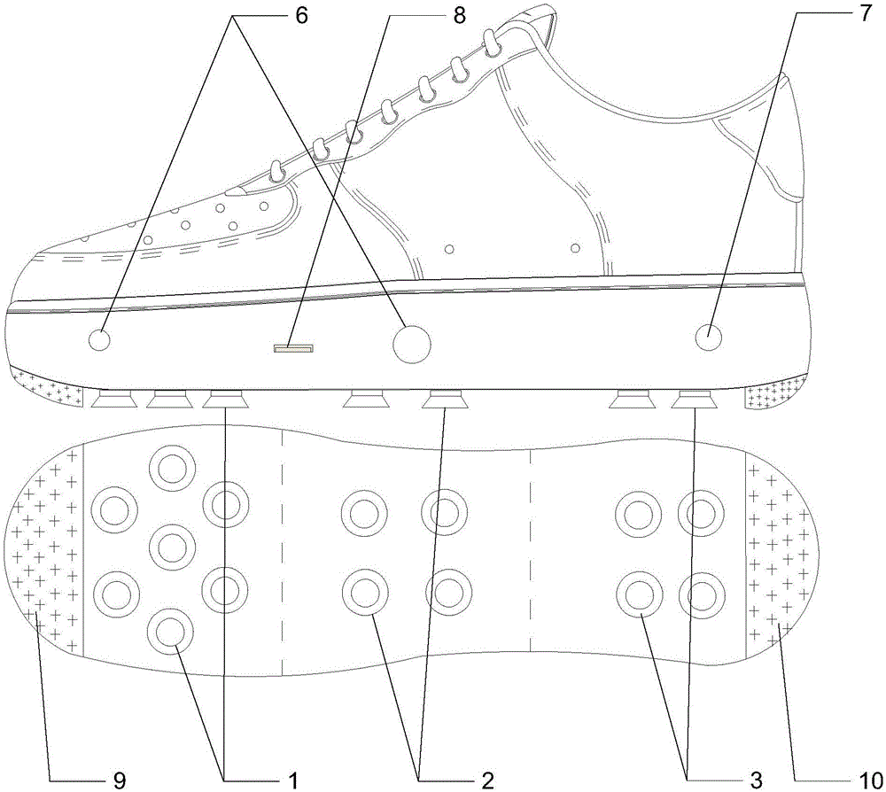
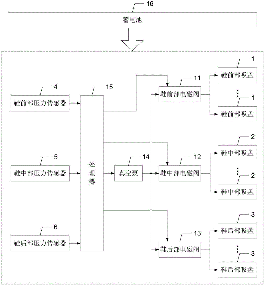
[0018] Specific implementation mode one: the following combination Figure 1 to Figure 3 Illustrate this embodiment, the special space special shoes for astronauts described in this embodiment, it comprises m shoe front suction cups 1, n shoe middle suction cups 2, k shoe rear suction cups 3, shoe front pressure sensors 4, Middle shoe pressure sensor 5, shoe rear pressure sensor 6, shoe front solenoid valve 11, shoe middle solenoid valve 12, shoe rear solenoid valve 13, vacuum pump 14 and processor 15;

[0019] m front shoe suction cups 1, n shoe middle suction cups 2 and k shoe rear suction cups 3 are respectively provided with the front, middle and rear areas of the bottom surface of the shoe;

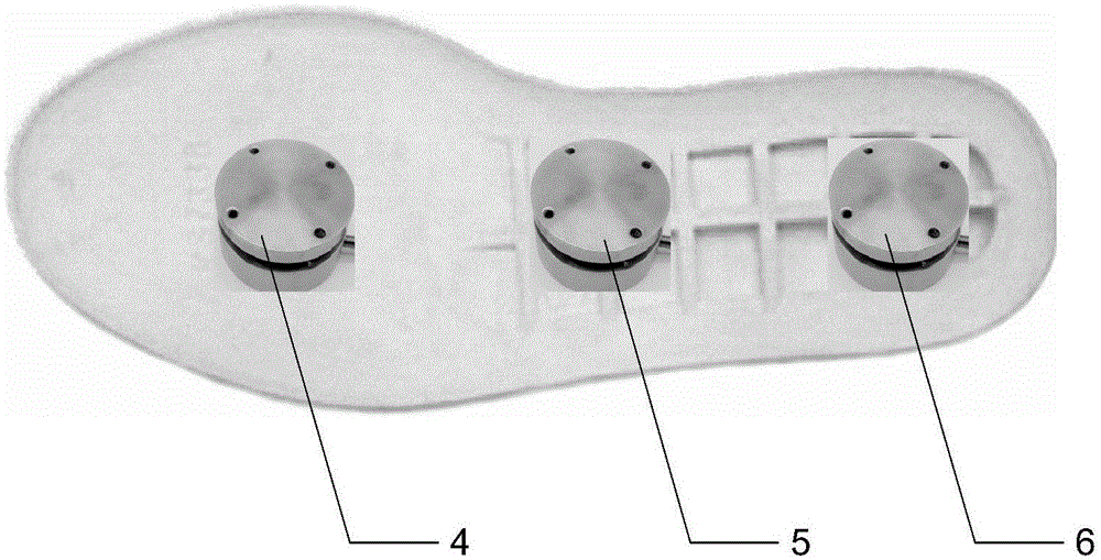
[0020] The front shoe pressure sensor 4, the middle shoe pressure sensor 5 and the shoe rear pressure sensor 6 are respectively provided with a hollow area of ​​the sole, and are used to detect the pressure signals of the front, middle and back of the foot;

[0021] The vacuum pump ...

specific Embodiment approach 2

[0037] Specific Embodiment 2: This embodiment will further explain Embodiment 1, and it also includes two air inlets 6 and exhaust ports 7, and the two air inlets 6 and exhaust ports 7 are arranged on the outer surface of the hollow area of ​​the shoe; The two air inlets 6 communicate with the air inlet of the vacuum pump 14; the air outlet 7 communicates with the air outlets of the m front shoe suction cups 1, the n shoe middle suction cups 2 and the k shoe rear suction cups 3.

specific Embodiment approach 3

[0038] Specific embodiment three: this embodiment will further explain embodiment one. It also includes a charging port 8 and a storage battery 16. The charging port 8 is arranged on the outer surface of the hollow area of ​​the shoe. The charging port 8 provides an external power inlet for the storage battery 16. The storage battery 16 provides a DC working power supply.

[0039] In this embodiment, the special shoes use the storage battery 16 as the power supply for the system, which can realize continuous charging and discharging, which not only saves energy consumption, but also realizes continuous use.

[0040] The battery 16 has a voltage of 10-15V and a capacity of 30,000mA, adopts fast charging technology, and the fastest charging completion time is 1.5-3h.


PUM


Abstract

The invention discloses a pair of space special shoes special for an astronaut, which belong to the aerospace field and aim to solve the problem that the astronaut can't stand stably in a space capsule. The pair of shoes comprise m suction discs at shoe front portions, n suction discs at shoe middle portions, k suction discs at shoe back portions, three pressure sensors, three electromagnetic valves, a vacuum pump and a processor, wherein the three pressure sensors are respectively used to detect pressure signals of front soles, middle portions of feet and heels and then send the signals to the processor; the processor is used to control the switch of the vacuum pump; an air output port of the vacuum pump is simultaneously communicated with air inlets of the m suction discs at the shoe front portions, n suction discs at the shoe middle portions and k suction discs at the shoe back portions through pipelines; the processor is used to send orders through the three electromagnetic valves and is used to respectively control the air on-off state and the size of the inlet air quantity of the m suction discs at the shoe front portions, the n suction discs at the shoe middle portions and the k suction discs at the shoe back portions.

Description

technical field [0001] The invention relates to a special shoe with vacuum negative pressure adsorption, which belongs to the field of aerospace. Background technique [0002] As my country's manned spaceflight has entered the stage of space station construction, the tasks of aerospace scientific research have become more arduous, making the astronauts' working hours in space continue to increase. have varying degrees of impact. Through the pictures sent back from the Tiangong cabin, we can see that it is difficult for the astronauts to control the stability of their walking. They can only fix their feet with a binding rope placed at a specific location, and the astronauts cannot stand steadily. At the same time, under space conditions, the human body is in a weightless floating state for a long time, which can easily accelerate the bone loss of astronauts. Contents of the invention [0003] The purpose of the present invention is to solve the problem that astronauts cann...

Claims


Application Information

Patent Timeline
Patent Type & Authority Applications(China)
IPC IPC(8): A43B3/00A43B13/14
Inventor 王振宇史旺
Owner HARBIN INST OF TECH
Why Eureka
Try Eureka