
Position adjustable internal nozzle device of quench machining tool

A quenching machine tool and inner nozzle technology, applied in quenching devices, heat treatment equipment, furnaces, etc., can solve the problems of poor hardening effect, cumbersome installation and operation, inconvenient installation and adjustment for workers, and achieve good structure and performance uniformity and process design Reasonable, the effect of reducing the number of equipment

Inactive Publication Date: 2015-11-04
HANDAN XINXING SPECIAL TUBING CO LTD
View PDF5 Cites 1 Cited by
  • Summary
  • Abstract
  • Description
  • Claims
  • Application Information

AI Technical Summary

Problems solved by technology

At present, the structure of the inner nozzle on the traditional quenching machine tool is single, the installation operation is cumbersome, and the design adopts a fixed connection method. Unsatisfactory. In actual production, on-site measurement, design and manufacture are required, which is troublesome and time-consuming
Moreover, with the long-term use of the equipment, the deviation of the production rotation position of the chain guide drive and the support wheel device of the quenching machine tool increases, resulting in a large alignment deviation between the inner nozzle and the center of the steel pipe, which makes the hardening effect of the entire length of the steel pipe poor. It is easy to bend in quenching water, and the temperature distribution of the steel pipe after quenching is uneven, which seriously affects the uniformity of structure and performance of the steel pipe.

Method used


Image

  • Position adjustable internal nozzle device of quench machining tool

Examples


Embodiment Construction

[0010] The technical solution of this patent will be described in further detail below in conjunction with specific embodiments.

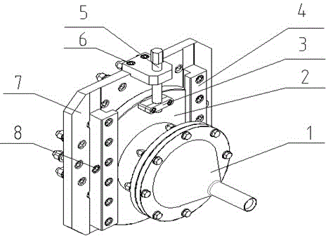
[0011] See figure 1 , A position-adjustable internal nozzle device of a quenching machine tool, comprising an internal nozzle 1, a sliding seat 2, a sliding seat rail 4, a screw rod 5 and a base flange 7; the sliding seat rail 4 is fixed on the base flange 7, There are two sliding seat rails 4, which are arranged in parallel and spaced apart. The sliding seat 2 is slidably installed between the two sliding seat rails 4. The gap between the two sliding seat rails 4 is greater than the width of the sliding seat 2, and the side of the sliding seat rail 4 There are bolt jacks 8 for adjusting the left and right positions of the sliding seat 2; the upper end of the base flange 7 is provided with a screw nut 6 for fixing and fixing the screw 5, the screw 5 is installed on the screw nut 6, sliding The seat 2 is provided with a positioning block 3, and the lo...


PUM


Abstract

The invention discloses a position adjustable internal nozzle device of a quench machining tool. The internal nozzle device comprises an internal nozzle, a sliding seat, sliding seat tracks, a screw rod and a base flange, wherein the two sliding seat tracks are fixed on the base flange in parallel at an interval, the sliding seat is glidingly mounted between the two sliding seat tracks, the interval between the two sliding seat tracks is larger than the width of the sliding seat, and bolt jackscrews for adjusting the left-right position of the sliding seat are arranged on the side surfaces of the sliding seat tracks; a screw rod nut for mounting and fixing the screw rod is arranged at the upper end of the base flange, the screw rod is mounted on the screw rod nut, a positioning block is arranged on the sliding seat, the lower end of the screw rod is connected to the positioning block, and a threaded hole in threaded fit with the screw rod is formed in the positioning block; the internal nozzle is assembled on the sliding seat. The position adjustable internal nozzle device of the quench machining tool is simple in structure, convenient to operate and wide in application range, and internal nozzles with different specifications can be replaced to meet quenching requirements of steel pipes with different specifications.

Description

Technical field [0001] The invention relates to an internal spray cooling device on a steel pipe quenching machine tool, in particular to an internal nozzle device of the quenching machine tool with adjustable position. Background technique [0002] The inner nozzle is a device to ensure the cooling of the inner wall of the quenched steel pipe, so that the inner and outer walls of the steel pipe have the same hardenability, increase the wall thickness of the steel pipe, and greatly reduce the distortion and bending of the steel pipe. At present, the internal nozzle on the traditional quenching machine tool has a single structure, and the installation operation is cumbersome. The design adopts a fixed connection method. It is not easy for workers to install and adjust. This results in a large number of internal nozzles equipped with specifications and quenching requirements for many non-standard steel pipe products. It cannot be satisfied. In actual production, on-site measure...

Claims


Application Information

Patent Timeline
Patent Type & Authority Applications(China)
IPC IPC(8): C21D1/667C21D9/08
Inventor 费志伟曹铜壁
Owner HANDAN XINXING SPECIAL TUBING CO LTD
Learn More