Machine tool

A technology of machine tools and pallets, applied in the field of machine tools, can solve problems such as long replacement time and complex structure of pallet replacement devices, and achieve the effect of simplifying the structure

Inactive Publication Date: 2015-11-04
OKUMA CORP
View PDF9 Cites 4 Cited by
  • Summary
  • Abstract
  • Description
  • Claims
  • Application Information

AI Technical Summary

Problems solved by technology

In such a case, it is conceivable that the structure of the pallet changing device becomes complicated due to the need for a control unit for synchronizing the pallet moving table with the transfer mechanism, etc.
[0008] In addition, in the above-mentioned pallet changing device, when the pallet is transferred between the pallet moving table and the table, it takes time to transfer the pallet between the pallet moving table and the transfer mechanism.
In such a case, it is conceivable that if the time taken for the delivery of the pallets is accumulated, the time required for changing between the pallet on which the processed workpiece is mounted and the pallet on which the workpiece before processing is mounted becomes longer.

Method used


Image

  • Machine tool
  • Machine tool
  • Machine tool

Examples


Embodiment approach 1

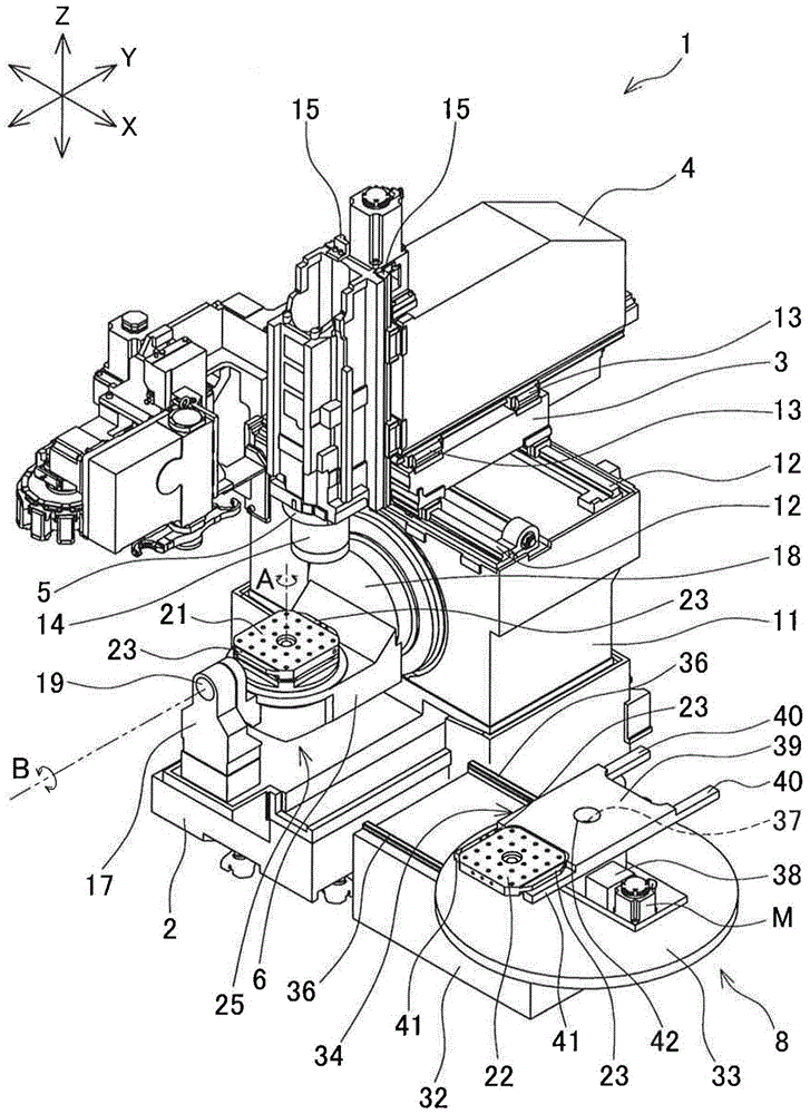
[0044] refer to Figure 1 to Figure 8 Embodiment 1 of the present invention will now be described. figure 1 with figure 2 The shown vertical machining center 1 includes a bed 2 , a saddle 3 , a column 4 , a headstock 5 , a table 6 , a main body cover 7 , a pallet changer 8 , and a side cover 9 . In addition, the vertical machining center 1 is an example of the machine tool of the present invention.

[0045] Such as figure 2 As shown, the bed 2 has a rectangular shape long in the front-rear direction (Y-axis direction) in plan view, and is installed on the floor. On the upper surface of the bed 2 and at the rear end of the bed 2, a rising portion 11 is provided to rise upward. A saddle 3 is provided on the upper surface of the standing portion 11 , and the saddle 3 is guided by the X-axis guide rails 12 , 12 so as to be movable in the left-right direction (X-axis direction). A column 4 is provided on the upper surface of the saddle 3 , and the column 4 is guided by a Y-a...

Embodiment approach 2

[0068] refer to Figure 9 to Figure 14 Embodiment 2 of the present invention will be described. Here, the same reference numerals are assigned to the same configurations as those in the first embodiment, and description thereof will be omitted. This vertical machining center 1A also includes a main body cover 7 and a side cover 9 , which are not shown. Such as Figure 9 As shown, a saddle 3A is provided on the front surface of the standing portion 11, and the saddle 3A is guided by X-axis guide rails 12A, 12A so as to be movable in the X-axis direction. A spindle head 5 is provided on the front surface of the saddle 3A, and the spindle head 5 is guided by Z-axis guide rails 15A, 15A so as to be movable in the Z-axis direction parallel to the axis of the spindle 14 .

[0069] On the upper surface of the bed 2 is provided with Figure 9 with Figure 11 Shown slide table 50, this slide table 50 is by Y-axis guide rail 13A, 13A (referring to Figure 10 ) to move in the front...


PUM


Abstract

A machine tool includes a pallet exchanger that is placed adjacent to one side of a body cover covering a workpiece machining space, and that exchanges a first pallet on which a machined workpiece is mounted and that is fixed to an upper surface of a table and a second pallet on which a workpiece to be machined is mounted. The pallet exchanger includes a turning member that has a first holding portion and a second holding portion formed in a pair and turns in a horizontal direction. The first holding portion is located at a first end of the turning member and holds the first pallet, and the second holding portion is located at a second end on the opposite side of the turning member from the first end and holds the second pallet.

Description

technical field [0001] The present invention relates to a machine tool which covers a processing space of the machine tool with a main body cover and has a pallet changing device which is provided adjacent to one side of the main body cover between a first pallet and a second pallet. Alternatively, the first pallet is equipped with processed workpieces fixed to the upper surface of the table arranged in the processing space, and the second pallet is mounted with unprocessed workpieces. Background technique [0002] For example, Patent Document 1 discloses a machine tool that uses a first cover to cover a machining space for workpieces provided on the machine tool body, and arranges a workbench with a workpiece fixed on its upper surface in the machining space. The second cover, which is continuous to the right side of the first cover, is equipped with a pallet changing device for placing a pallet on which processed workpieces are fixed on the upper surface of the workbench a...

Claims


Application Information

Patent Timeline
Patent Type & Authority Applications(China)
IPC IPC(8): B23Q1/00
CPCB23Q7/02B23Q1/44B23Q11/0891B23Q7/1431B23Q7/1494Y10T29/5196Y10T409/30392Y10T409/305824Y10T409/308288Y10T409/309576Y10T483/16Y10T483/1755B23Q1/5406B23Q1/626B23Q3/15766
Inventor 村田笃哉
Owner OKUMA CORP
Why Eureka
Try Eureka