
Automatic tin soldering device

An automatic welding and soldering technology, which is applied in the directions of tin feeding devices, welding positions, welding equipment, etc., can solve the problems of pipe blockage, deviation feeding, and low tin feeding position accuracy, and achieves good processing accuracy, simple appearance, and easy replacement. Effect

Inactive Publication Date: 2015-11-04
浙江兴盛铸造有限公司
View PDF6 Cites 1 Cited by
  • Summary
  • Abstract
  • Description
  • Claims
  • Application Information

AI Technical Summary

Problems solved by technology

[0002] The current automatic or semi-automatic soldering generally uses a soldering iron to directly heat the workpiece to be welded, and the tin feeding wire is sent from the side of the soldering iron through a conduit to achieve the purpose of welding. The disadvantage is that the structure of the soldering wire is o

Method used


Image

  • Automatic tin soldering device
  • Automatic tin soldering device
  • Automatic tin soldering device

Examples


Example Embodiment

[0015] The preferred embodiments of the present invention will be described in detail below in conjunction with the accompanying drawings.

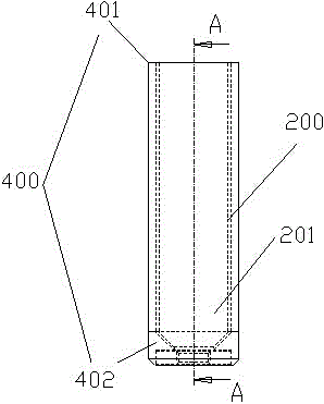
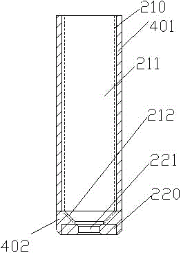
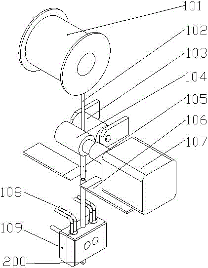
[0016] The invention provides an automatic soldering device with a structure such as image 3 As shown, it includes a soldering device for transferring a tin wire and a heating device for heating an electric soldering iron to melt the tin wire, as well as the aforementioned soldering iron tip 200, such as figure 2 As shown, the soldering iron tip 200 is connected to a heating device for sending out molten solder. A cutting knife 106 can be arranged between the tin feeding device and the heating device, such as image 3 As shown, it is used to cut the tin wire that needs to be melted. When used, it can be cut according to needs, and the supply of tin wire can be controlled more accurately than fusing solder wire.

[0017] Among them, the tin feeding device may specifically be a tin feeding wire idler 103 and a tin feeding wire driving wheel 10...


PUM


Abstract

The invention discloses an automatic tin soldering device. The automatic tin soldering device comprises a tin feeding device for conveying tin wires and a heating device for melting the tin wires, and further comprises a soldering bit on the frontal surface, wherein the soldering bit is connected with the heating device for feeding the molten soldering tin to a welding point; a soldering bit body is coated with a fixed sleeve; a first mounting position for fixing a tin hating piece and a second mounting position for fixing a tin loving piece are arranged in the fixed sleeve; the first mounting position is a cylindrical structure; the second mounting position is a chamfering angle structure; the tin hating piece is tightly bonded with the inner surface of the first mounting position; the tin loving piece is tightly bonded with the inner surface of the second mounting position; and the tin loving piece and the tin hating piece are fixedly connected through threads, so that a first tin soldering runner and a second tin soldering runner are in seamless butt joint. The automatic tin soldering device can conveniently replace the soldering bit; and meanwhile, the automatic tin soldering device having the soldering bit adopts a cutter to cut off the soldering tin so as to precisely control the supply quantity of the soldering tin as required.

Description

technical field [0001] The invention relates to a welding device, in particular to an automatic soldering device. Background technique [0002] The current automatic or semi-automatic soldering generally uses a soldering iron to directly heat the workpiece to be welded, and the tin feeding wire is sent from the side of the soldering iron through a catheter to achieve the purpose of welding. The disadvantage is that the structure of the tin feeding wire is outside the tip of the soldering iron. There is a certain tolerance between the inner diameter and the outer diameter of the tin wire. The accuracy of the tin feeding position is not high, and deviation may occur. If the conduit is too close to the tip of the soldering iron, the conduit may be blocked by flux volatiles. Therefore it is necessary to improve the prior art. Contents of the invention [0003] The object of the present invention is to provide an automatic soldering device which can improve the accuracy of sol...

Claims


Application Information

Patent Timeline
IPC IPC(8): B23K3/02B23K3/06
CPCB23K3/025B23K3/063
Inventor 郭锦炎
Owner 浙江兴盛铸造有限公司
Learn More