
Spiral separation type sewage treatment plant

A sewage treatment device and spiral separation technology, applied in the direction of centrifugal separation water/sewage treatment, filtration separation, separation method, etc., can solve the problems of large construction area of ​​sedimentation tank, long sedimentation time, blocked application, etc., and achieve good treatment effect, High separation efficiency and simple appearance

Inactive Publication Date: 2017-11-24
丁蒙蒙
View PDF0 Cites 11 Cited by
  • Summary
  • Abstract
  • Description
  • Claims
  • Application Information

AI Technical Summary

Problems solved by technology

[0002] As a part of municipal construction, sewage treatment is an effective measure to ensure environmental health. However, due to the use of natural precipitation and chemical precipitation in traditional sewage treatment, the precipitation time is long and the precipitation is difficult to separate. application blocked
[0003] In order to solve the above-mentioned problems, the present invention is proposed, which overcomes the problems of the traditional sewage treatment device, such as the adoption of sedimentation and filtration, the long sedimentation time and the large construction area of ​​the sedimentation tank, and solves the problems of the traditional sewage treatment device. , causing problems such as incomplete precipitation and difficult separation, which improves the traditional sewage treatment device. Due to the imperfect transmission design, the transmission elements are exposed to the outside, which reduces the service life of the device, making the present invention novel in structure and simple in appearance. Stable transmission, centrifugal filtration instead of traditional sedimentation filtration, high separation efficiency, good treatment effect, etc.

Method used


Image

  • Spiral separation type sewage treatment plant
  • Spiral separation type sewage treatment plant
  • Spiral separation type sewage treatment plant

Examples


Embodiment Construction

[0018] The following will clearly and completely describe the technical solutions in the embodiments of the present invention with reference to the accompanying drawings in the embodiments of the present invention. Obviously, the described embodiments are only some, not all, embodiments of the present invention. Based on the embodiments of the present invention, all other embodiments obtained by persons of ordinary skill in the art without making creative efforts belong to the protection scope of the present invention.

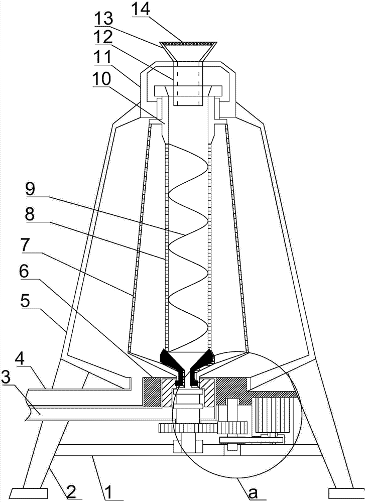
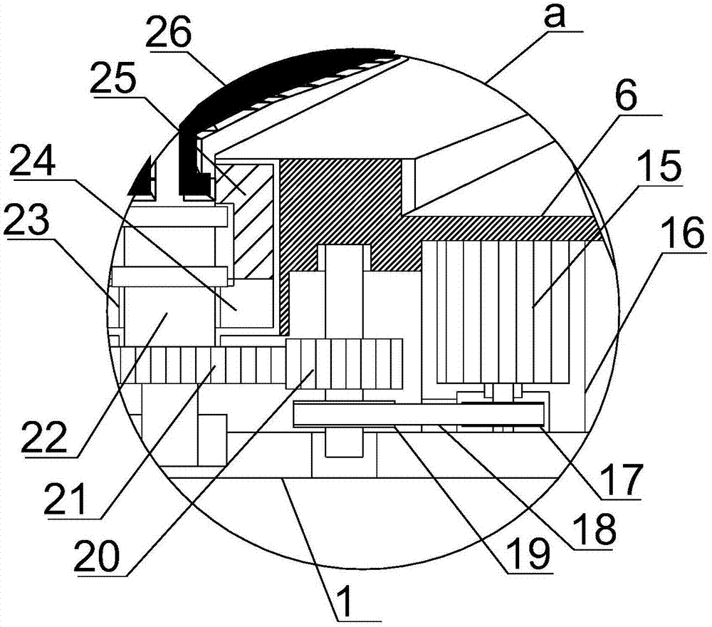
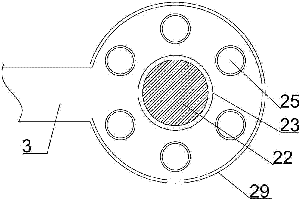
[0019] see Figure 1~4 , in an embodiment of the present invention, a spiral separation type sewage treatment device includes a support installation module, a water inlet separation module and a centrifugal transmission module, the support installation module includes a support installation cylinder 5, and the upper end of the support installation cylinder 5 is uniform A number of air guide holes are provided, and the lower end of the support installation cyli...


PUM


Abstract

The invention discloses a spiral separation type sewage treatment device, which comprises a support installation module, a water inlet separation module and a centrifugal transmission module. The lower end of the cylinder is provided with supporting columns obliquely and symmetrically at the left and right ends, and a transmission support installation plate is horizontally arranged between the lower half of the support columns on the left and right sides. The water inlet separation module is arranged on the support installation cylinder, and the water inlet separation The module includes a feed protection cover arranged on the upper end of the support installation cylinder, a centrifugal filter cartridge is vertically arranged at the lower end of the feed protection cover in conjunction with the support installation cylinder, and a limited rotation feed ring is arranged on the upper end of the centrifugal filter cylinder in conjunction with the feed protection cover. The invention has the advantages of novel structure, simple appearance, stable transmission, centrifugal filtration instead of traditional sedimentation filtration, high separation efficiency and good treatment effect.

Description

technical field [0001] The invention relates to municipal sewage treatment equipment, in particular to a spiral separation sewage treatment device. Background technique [0002] As a part of municipal construction, sewage treatment is an effective measure to ensure environmental health. However, due to the use of natural precipitation and chemical precipitation in traditional sewage treatment, the precipitation time is long and the precipitation is difficult to separate. Application blocked. [0003] In order to solve the above-mentioned problems, the present invention is proposed, which overcomes the problems of the traditional sewage treatment device, such as the adoption of sedimentation and filtration, the long sedimentation time and the large construction area of ​​the sedimentation tank, and solves the problems of the traditional sewage treatment device. , causing problems such as incomplete precipitation and difficult separation, which improves the traditional sewage...

Claims


Application Information

Patent Timeline
IPC IPC(8): B01D33/067B01D33/11B01D33/72C02F1/38
CPCB01D33/067B01D33/11B01D33/72C02F1/001C02F1/38
Inventor 丁蒙蒙
Owner 丁蒙蒙
Learn More