Chain feeding square tube punching machine

A punching machine and punching technology, applied in the field of machinery, can solve the problems of irregular material, short die life, difficult to arrange neatly, etc., and achieve the effect of neat and regular arrangement, high production efficiency, and easy management.

Inactive Publication Date: 2015-11-04
苏州金牛精密机械有限公司
View PDF6 Cites 4 Cited by
  • Summary
  • Abstract
  • Description
  • Claims
  • Application Information

AI Technical Summary

Problems solved by technology

[0002] Pipe punching is traditionally done manually by ordinary punching machines or bench drills. This processing method has the problems of low efficiency and poor product quality, and the labor intensity of the workers is high, the life of the mold is short, and the safety of the operators is difficult to obtain. Guarantee, some safety accidents are prone to occur, high labor cost, high power consumption
The feeding mechanism of the square tube punching machine is generally conveyed by a belt, which is not easy to arrange neatly, the material is irregular, the punching mechanism cannot be positioned accurately, and the punching is prone to deviation. During the feeding process of the square tube punching machine, it is necessary to ensure the transmission The square tubes are arranged neatly with the same spacing

Method used


Image

  • Chain feeding square tube punching machine
  • Chain feeding square tube punching machine
  • Chain feeding square tube punching machine

Examples


Embodiment Construction

[0017] The present invention will be further described below in conjunction with accompanying drawing:

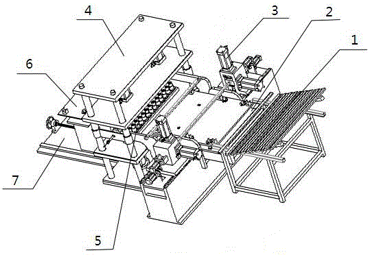
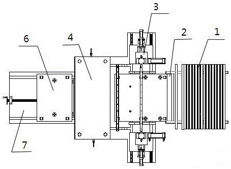
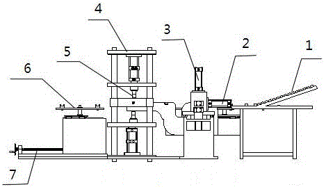
[0018] A square tube punching machine, characterized in that it includes a material accumulation area 1, a material finishing structure 2, an end punching mechanism 3, a punching hydraulic frame 4, a punching die 5, a moving frame for unloading finished products 6, and a moving frame for changing molds 7. Equipped with a PLC controller and equipped with a touch screen, and the material accumulation area 1 is equipped with a chain feeding mechanism, the chain feeding mechanism includes a feeding table 8, a finishing chain 9, a floating cylinder 10 is set under the right end of the feeding table 8, and a floating cylinder 10 is set at the left end of the feeding table 8 The first material retaining plate 11; also comprise motor 12, motor control finishing chain 9 rotates; Feeding platform 8 left ends are provided with conveying chain 13, conveying chain 13 middle part tops are...


PUM


Abstract

The invention provides an automatic square tube punching machine with high production efficiency. To solve the technical problem, the invention adopts a technical scheme that the square tube punching machine is characterized by comprising a material stacking area, a material arrangement structure, end punching mechanisms, a punching hydraulic rack, a punching die, a finished product discharging movable frame and a die replacement movable frame; a PLC is arranged, and is provided with a touch screen; a chain feeding mechanism is arranged in the material stacking area and comprises a feeding table and an arrangement chain; a floating air cylinder is arranged below the right end of the feeding table, and a first blocking plate is arranged at the left end of the feeding table; a motor is further arranged, and controls the arrangement chain to rotate; a conveying chain is arranged at the left end of the feeding table, and a second blocking plate is arranged above the middle of the conveying chain. The square tube punching machine has the beneficial effects that the machine can arrange the square tubes automatically, orderly, and regularly; precise locating of the punching mechanisms is achieved, and the deviation is not prone to occur; the automatic production is achieved, the management is facilitated, the efficiency is high, and the safety of operators is guaranteed.

Description

technical field [0001] The invention relates to the technical field of machinery, in particular to a square tube punching machine. Background technique [0002] Pipe punching is traditionally done manually by ordinary punching machines or bench drills. This processing method has the problems of low efficiency and poor product quality, and the labor intensity of the workers is high, the life of the mold is short, and the safety of the operators is difficult to obtain. Guarantee, some safety accidents are prone to occur, the labor cost is high, and the power consumption is high. The feeding mechanism of the square tube punching machine is generally conveyed by a belt, which is not easy to arrange neatly, the material is irregular, the punching mechanism cannot be positioned accurately, and the punching is prone to deviation. During the feeding process of the square tube punching machine, it is necessary to ensure the transmission The square tubes are arranged neatly and equal...

Claims


Application Information

Patent Timeline
Patent Type & Authority Applications(China)
IPC IPC(8): B21D28/34B21D28/28B21D43/12
Inventor 周建荣
Owner 苏州金牛精密机械有限公司
Why Eureka
Try Eureka