
Photo-acoustic endoscopic apparatus based on graded-index optical fiber

A gradient type, optical fiber technology, applied in endoscopy, medical science, surgery, etc., can solve the problems of limiting the minimum outer diameter and stem length of the photoacoustic endoscopy device, restricting the imaging speed of the system, and increasing the difficulty of system assembly. Achieve the effect of simple assembly, small size and reduced divergence angle

Active Publication Date: 2015-11-04
SHENZHEN INST OF ADVANCED TECH
View PDF8 Cites 3 Cited by
  • Summary
  • Abstract
  • Description
  • Claims
  • Application Information

AI Technical Summary

Problems solved by technology

If the single pulse energy is increased, on the one hand, the system’s choice of tunable lasers is limited, and on the other hand, the imaging speed of the system is severely restricted, and the imaging speed is slow
The introduction of a self-focusing lens to converge the outgoing beam of the step-type optical fiber will greatly improve the signal-to-noise ratio and resolution of the system, enabling the system to use a tunable laser with a higher repetition rate to obtain high-speed imaging. However, at the same time Limits the minimum outer diameter and dry length of the photoacoustic endoscopy device, increasing the difficulty of system assembly

Method used


Image

  • Photo-acoustic endoscopic apparatus based on graded-index optical fiber
  • Photo-acoustic endoscopic apparatus based on graded-index optical fiber
  • Photo-acoustic endoscopic apparatus based on graded-index optical fiber

Examples


Embodiment Construction

[0025] The technical means adopted by the present invention to achieve the intended invention purpose are further described below in conjunction with the drawings and preferred embodiments of the present invention.

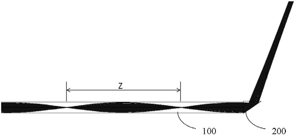
[0026] see figure 1 , the photoacoustic endoscopic device based on the gradient optical fiber provided by the embodiment of the present invention includes a gradient optical fiber 100 , a reflection mechanism 200 , an ultrasonic transducer 300 and a protective sheath 400 . Wherein, the output end of the gradient optical fiber 100, the reflection mechanism 200, and the ultrasonic transducer 300 are sequentially fixed in the protective sleeve 400. The ultrasonic transducer 300 receives the photoacoustic signal generated at the target tissue and converts it into an electrical signal for output. figure 2 Shown is the optical path simulation diagram of the gradient fiber-based photoacoustic endoscopic device provided in this embodiment.

[0027] Gradient optical fib...


PUM


Abstract

The invention provides a photo-acoustic endoscopic apparatus based on a graded-index optical fiber. The photo-acoustic endoscopic apparatus based on graded-index optical fibers comprises the graded-index optical fiber, a reflecting mechanism, an ultrasonic transducer and a protective sleeve. An emergent end of the graded-index optical fiber, the reflecting mechanism and the ultrasonic transducer are sequentially fixed into the protective sleeve. Lasers, emergent from the emergent end of the graded-index optical fiber, are reflected by the reflecting mechanism and converged at the target tissue outside of the protection sleeve in order to generate a photo-acoustic signal by simulation of the target tissue. The ultrasonic transducer receives the photo-acoustic signal generated at the target tissue and coverts the photo-acoustic signal into an electric signal for output. The photo-acoustic endoscopic apparatus based on the graded-index optical fiber has following beneficial effects: the graded index fiber is utilized for laser transmission without introducing other convergent components so that convergence of the emergent lasers is achieved. The decrease in divergence angles of the emergent lasers gives rise to increase in pulsed light quantity incident upon the surface of the target tissue. Therefore, imaging signal-to-noise ratio and imaging speed of a system are effectively increased. The photo-acoustic endoscopic apparatus is small in size and simple in assembly.

Description

technical field [0001] The invention relates to the technical field of photoacoustic imaging, in particular to a photoacoustic endoscopic device based on a gradient optical fiber. Background technique [0002] Photoacoustic imaging technology obtains information about the light absorption of biological tissue by detecting the ultrasonic signal (ie, photoacoustic signal) generated by the transient thermoelastic effect after the tissue absorbs the pulsed laser. In the case of constant excitation illumination parameters, the intensity and frequency spectrum of photoacoustic signals are closely related to the optical properties (mainly light absorption properties) of biological tissues. Different tissues have different light absorption characteristics, so photoacoustic imaging can perform high-contrast structural imaging of specific components in tissues. The contrast of photoacoustic imaging comes from light absorption, while the resolution mainly comes from ultrasonic signals...

Claims


Application Information

Patent Timeline
IPC IPC(8): A61B1/00A61B1/04A61B1/07
Inventor 李岩龚小竞宋亮
Owner SHENZHEN INST OF ADVANCED TECH
Learn More