
Wireless power supply system and wireless power supply apparatus

A technology for wireless power supply and power supply device, which is applied to circuit devices, electromagnetic wave systems, electrical components, etc., can solve the problems of reduced power supply efficiency, increased high-frequency output, and increased rectifier loss, etc., to achieve the effect of improving power supply efficiency.

Inactive Publication Date: 2015-10-28
RESONAC HOLDINGS CORPORATION
View PDF6 Cites 2 Cited by
  • Summary
  • Abstract
  • Description
  • Claims
  • Application Information

AI Technical Summary

Problems solved by technology

The AC current (electric power) passing through the diode is consumed by smoothing capacitors, etc., resulting in a decrease in the power efficiency of the power supply.
In order to provide large power, it is conceivable to increase the high-frequency output on the power supply side, but as the high-frequency output increases, the loss of the rectification part also increases, so the power efficiency cannot be improved.
In addition, the increase of high-frequency output may cause damage to the smoothing capacitor

Method used


Image

  • Wireless power supply system and wireless power supply apparatus
  • Wireless power supply system and wireless power supply apparatus
  • Wireless power supply system and wireless power supply apparatus

Examples


Embodiment Construction

[0024] Embodiments of the invention will be described below with reference to the drawings. In the embodiment, in order to improve the power efficiency of high-frequency power supply with a simple structure, the mixed wave generator 21 is used as an AC power supply.

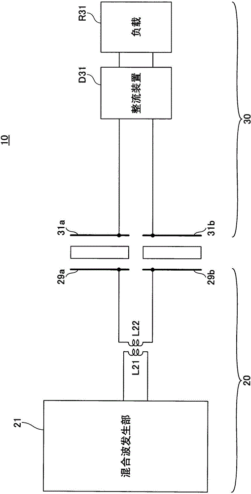
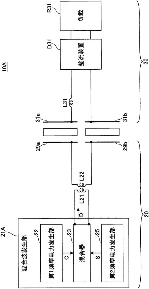
[0025] figure 1 It is a schematic block diagram of the wireless power feeding system 10 according to the embodiment of the present invention. The wireless power supply system 10 includes a power supply device 20 and a power receiving device 30 . As an example, the wireless power feeding system 10 adopts an electric field coupling method. The power supply device 20 has power supply electrodes 29a, 29b, and the power reception device 30 has power reception electrodes 31a, 31b. The power feeding electrodes 29a, 29b and the power receiving electrodes 31a, 31b are, for example, flat plate electrodes, which can be formed with any thickness using any material such as metal, metal oxide, or carbon. The feeding electr...


PUM


Abstract

Disclosed is a system wherein power is supplied from a power supply apparatus to a power receiving apparatus in a non-contact manner. The power supply apparatus supplies, at one time, alternating current power having at least two different frequencies, and the power receiving apparatus has a rectifying circuit that rectifies the supplied alternating current power into a direct current.

Description

technical field [0001] The present invention relates to a wireless power supply system and a wireless power supply device for wirelessly supplying electric power to a power receiving device. Background technique [0002] In recent years, there has been active research on wireless power supply systems that can supply electric power to electric vehicles, portable devices, flat-screen TVs, etc. without using wiring cables. In particular, attention has been paid to an electric field coupling method in which a battery of a target device can be charged without contact between a power-transmitting electrode that supplies power and a power-receiving electrode that receives power (see, for example, Patent Document 1 and Patent Document 2). [0003] As the non-contact power feeding method, there are electromagnetic induction method, magnetic resonance method, etc. other than the electric field coupling method. This has the advantage that when wireless power feeding is performed using...

Claims


Application Information

Patent Timeline
Patent Type & Authority Applications(China)
IPC IPC(8): H02J17/00
CPCH02J17/00H02J50/10H02J50/12H02J50/05H02J50/20
Inventor 民野泰秋时田孝二光本龙一小沼博西冈绫子今泉光博
Owner RESONAC HOLDINGS CORPORATION
Learn More